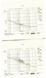
Here is battery powered Groner preamp with shorted input in Hammond box. Input devices LSK170Ax8. Output of the amp is connected to AP with balanced cable. Measurements done in three positions of the box, along X,Y and Z axis. Input ckt (with decoupling large cap) works as a magnetic field sensor.
You are also joining the club of those that were completely unable to reproduce Groner's claim of 0.5nV/rtHz @ 10 Hz LF noise and a noise corner frequency of well under 100Hz. Your results (2...3nV/rtHz) are in line with what everybody else got with this preamp (with mine as well). This is another mystery that I was never able to figure out, and Groner was not at all helpful (nice way to say he brushed off the question with "read the LA article").
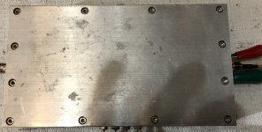
Aluminum is helpful for shielding the magnetic field, if you do like myself and mill a 12mm thick walls case out of a 2" thick of 6061 aluminum plate. That was the only way (called Faraday shielding) I was able to lower the mains harmonics to 2uV output, with a gain of 60dB (2nV input equivalent). With an identical SE setup (but with batteries), Hans and Groner got much less mains harmonics (invisible on the spectra) practically without any magnetic filed shielding to speak of.
this loop isn't amplified by 60dB, as the input oneThe battery wiring forms nice loop antennas and the resulting hum currents
The amplification factor is not well defined. It depends on the ground plane impedance and where in the signal ground path the hum voltage is produced: if it is in the input part of the amp (e.g. hum voltage is created between input terminal ground pin and source resistor of the FETs), it may get the full amplification and if it is at the output, it gets no amplification at all
12mm thick walls case out of a 2" thick of 6061 aluminum plate
I'm going to order zero-gauss chamber from magnetic shield
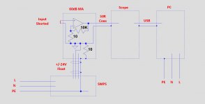
For what it's worth, here the noise spectrum of my MA when powered with a +/-24V SMPS, taken under exactly the same conditions as before:
fs=2MHz, bin width 0.93Hz, output to scope with a 50R Coax.
.
A noise baseline at -210 dBV = 35 pV/rt Hz seems optimistic to me.
Fred Walls of NIST needed cross correlation to reach -205 dBV for his
battery noise measurements.
😕 Gerhard
It might be even a bit more complex.Most probably, the SMPS creates a common mode hum signal on the power supply ground line. This ground is going into the MA and from there over the coax cable shield to the scope / spectrum analyzer. The resulting hum current creates the signal visible in the spectrum. This signal is independant from the regulators used - they do exactly what they should do by keeping V+ and V- rock solid referenced to the ground line. But it is the ground line which causes the hum problem. As soon as the amp is battery suplied, no hum current coming from mains is injected into the ground line and the resulting spectra are hum free.
On the primary side, the SMPS box is connected to PE.
Looking at the picture shows that the cable shielding and connector shell on the secondary side are also connected to PE, but the produced voltages are all floating.
This PE is connected to the MA's enclosure and to prevent gnd loops through a 10R resistor to the signal gnd.
The shield of the coax cable going to the scope is also directly connected to PE through the PC and in effect ties the MA's signal gnd to PE.
Since a picture tells more than a thousand words, I made the sketch below.
Hans
.
Attachments
I'm going to order zero-gauss chamber from magnetic shield
That would be interesting to play with. I would think they are expensive, though, any idea?
That -211dB should be seen in the context of the thread.A noise baseline at -210 dBV = 35 pV/rt Hz seems optimistic to me.
Fred Walls of NIST needed cross correlation to reach -205 dBV for his
battery noise measurements.
😕 Gerhard
With the 34dB gain of the HA and the 60dB of the MA, I made this 94dB attenuation to show how much the MA's noise was below the -190dB HA's noise.
That proved that the noise contribution of the MA could be neglected at 20dB below.
To get the correct value, one should add 34dB to the -211dB or 1.4nV/rtHz.
Hans
What happens to the mains harmonics when you disconnect pin1 on the AP side and connect the Hammond box to PE ?Here is battery powered Groner preamp with shorted input in Hammond box. Input devices LSK170Ax8. Output of the amp is connected to AP with balanced cable. Measurements done in three positions of the box, along X,Y and Z axis. Input ckt (with decoupling large cap) works as a magnetic field sensor.
That's how I made the connection.
Hans
Removing the lid
Below is the output of my MA (input shorted) with and without the lid to the heavy (12mm) shielding lid (photos also attached). Everything is exactly the same, measurements takes 5 minutes apart.
60Hz is 20dB higher with the lid off, plus tons of LF grass (likely mains harmonics intermodulation products).
Definitely a magnetic field effect. It's either my place is heavily polluted, or Hans and Groner live in one of those mumetal enclosures. I hope it is clear now why I believe batteries won't help.
Attachments
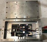
Dimitri,Here is battery powered Groner preamp with shorted input in Hammond box. Input devices LSK170Ax8. Output of the amp is connected to AP with balanced cable. Measurements done in three positions of the box, along X,Y and Z axis. Input ckt (with decoupling large cap) works as a magnetic field sensor.
Could you be so kind to tell what version Groner preamp is it that you made ?
I went to his website and found many designs, or is it the one published in Linear Audio Vol3 ?
Is it really differential or just balanced, and how was the connection made to the enclosure, through caps or directly to the PCB's ground plane.
Hans
yes, the one published in Linear Audio Vol3
The input and output are SE, input shorted, balanced pair to AP comes from the preamp output and preamp ground. Enclosure is connected to pin 1 and has no connection to preamp ground. I made measurements with preamp ground connected to pin 1 and without - no difference.
The input and output are SE, input shorted, balanced pair to AP comes from the preamp output and preamp ground. Enclosure is connected to pin 1 and has no connection to preamp ground. I made measurements with preamp ground connected to pin 1 and without - no difference.
you would like to disconnect AP chassis from cable shield and box?😕when you disconnect pin1 on the AP side
At last some convincing facts for an SE MA amp that pollution in your case comes from the outside world.Below is the output of my MA (input shorted) with and without the lid to the heavy (12mm) shielding lid (photos also attached). Everything is exactly the same, measurements takes 5 minutes apart.
60Hz is 20dB higher with the lid off, plus tons of LF grass (likely mains harmonics intermodulation products).
Definitely a magnetic field effect. It's either my place is heavily polluted, or Hans and Groner live in one of those mumetal enclosures. I hope it is clear now why I believe batteries won't help.
Since I am not living in a mumetal enclosure, conclusion can only be that you are living in a highly polluted area.
I'm living in a former farmhouse where the 5 nearest houses are 50 meters or more from my place with central electricity provision all around coming from under the ground.
No windmills or GSM transmitters nearby, so yes I can very well imagine that my place is relatively free from radiation.
Hans
yes, the one published in Linear Audio Vol3
The input and output are SE, input shorted, balanced pair to AP comes from the preamp output and preamp ground. Enclosure is connected to pin 1 and has no connection to preamp ground. I made measurements with preamp ground connected to pin 1 and without - no difference.
you would like to disconnect AP chassis from cable shield and box?😕
Thank you for the info.
I'll read the Groners article first before I come back.
Hans
yes, the one published in Linear Audio Vol3
The input and output are SE, input shorted, balanced pair to AP comes from the preamp output and preamp ground. Enclosure is connected to pin 1 and has no connection to preamp ground. I made measurements with preamp ground connected to pin 1 and without - no difference.
you would like to disconnect AP chassis from cable shield and box?😕
With your battery powered MA, the enclosure is connected to PE via your cable's pin 1 on both sides through the AP chassis.
Not making a connection to signal gnd means that your MA is in fact floating.
I would prefer a situation where:
1) The MA's signal gnd is connected to the enclosure
2) The enclosure has its own connection to PE
3) And to prevent gnd loops, that the cable shielding starting at pin 1 from the MA, goes all the way to the AP, but is disconnected from pin 1 at the receiving side. Only the two balanced lines should enter the AP balanced input and nothing else.
That gave me the best possible reduction in mains pollution.
But when living in or near Toronto, you will probably need a much better shielding and a beautifully milled one billet alu box 😀
Hans
Further to my earlier answer, I wonder how in your situation a Diff topology would help to tame these so called "LF grass" pollutions.Below is the output of my MA (input shorted) with and without the lid to the heavy (12mm) shielding lid (photos also attached). Everything is exactly the same, measurements takes 5 minutes apart.
60Hz is 20dB higher with the lid off, plus tons of LF grass (likely mains harmonics intermodulation products).
Definitely a magnetic field effect. It's either my place is heavily polluted, or Hans and Groner live in one of those mumetal enclosures. I hope it is clear now why I believe batteries won't help.
When induced with the same polarity in both Diff paths, it should be possible to remove them in a later stage when converting from Diff to Se as in my HA, wouldn't it ?
If so, it would at least partly explain why my HA without enclosure is so free of pollution.
Hans
P.S. I love your Alu Enclosure. Is that a standard product somewhere or was it ready made for you?
Is that a standard product somewhere or was it ready made for you?
Made it myself, I have a CNC milling machine.
And to prevent gnd loops, that the cable shielding starting at pin 1 from the MA, goes all the way to the AP, but is disconnected from pin 1 at the receiving side. Only the two balanced lines should enter the AP balanced input and nothing else.
What loops, Hans? Are you suggesting to keep cable shield and MA box float?
Attachments
What loops, Hans? Are you suggesting to keep cable shield and MA box float?
That would be a very, very bad idea. Probably worse than no shielding at all.
- Home
- Source & Line
- Analogue Source
- Richard Lee's Ultra low Noise MC Head Amp