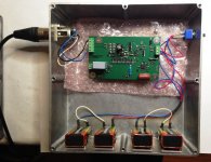
-Unshielded HA on mouse pad, powered from 5W USB adapter having no direct connection with signal gnd (called Null here), see second image below.
-HA diff input terminated with 1R resistor, no cable connected at this side
-connection between HA and MA with 60cm Siltech FTM4 Gold cable with WBT RCA connectors, driven from HA's Diff to SE converter.
-Connection between MA and scope a 60cm 50R coax cable.
The mystery remains.
Short of irrelevant details (like the cable manufacturer), the only difference to my measurement setup is that your SE MA is battery powered, mine is not. I see mains harmonics even with the MA input shorted (no HA), see #1609, and 30cm of shielded cable (also shorted) makes the mains harmonics x5 worse.
I would need lots of batteries to feed my MA since it needs +/-20V or more from the external power supply but I will try sometime. Until, I give up admitting I have no idea what's happening.
There is no mystery, it's just a matter of not giving up until you have what you aim for.The mystery remains.
Short of irrelevant details (like the cable manufacturer), the only difference to my measurement setup is that your SE MA is battery powered, mine is not. I see mains harmonics even with the MA input shorted (no HA), see #1609, and 30cm of shielded cable (also shorted) makes the mains harmonics x5 worse.
I would need lots of batteries to feed my MA since it needs +/-20V or more from the external power supply but I will try sometime. Until, I give up admitting I have no idea what's happening.
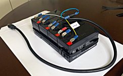
I've given you as many details as possible and now as a last step I show you my MA battery solution.
Four 12V/1.3Ah batteries are tied together to give me +/-24 Volt, simple as it can be, also perfectly suited for your MA so it seems.
Give it a try and I'm sure you will make a big step forward.
Succes,
Hans
.
Attachments
There is no mystery, it's just a matter of not giving up until you have what you aim for.
I'm not necessary interested for a solution for an otherwise non existent problem (no big deal to have 2nV input referred mains harmonics) but more like identifying the root cause for the observed behavior in my lab. That's the mistery. You (and others) appear not to have this problem (for unclear reasons), good for you, others seem to have the same problem (for unclear reasons as well).
I'm not necessary interested for a solution for an otherwise non existent problem (no big deal to have 2nV input referred mains harmonics) but more like identifying the root cause for the observed behavior in my lab. That's the mistery. You (and others) appear not to have this problem (for unclear reasons), good for you, others seem to have the same problem (for unclear reasons as well).
Just buy 4 batteries as shown if you want to switch from the pollution troubled camp into the flat noise camp.
I would be disappointed if you didn’t, after having answered in much detail so many of your questions.
After the Nichicon revelation, this could be the next step.
Hans
Just buy 4 batteries as shown if you want to switch from the pollution troubled camp into the flat noise camp.
I would be disappointed if you didn’t, after having answered in much detail so many of your questions.
After the Nichicon revelation, this could be the next step.
I agree feeding the MA from betteries won't harm. But before investing $100 in 4 x 12V rechargeable batteries I need to understand what is happening, since no ground loops exist.
Please do a small effort and avoid the patronizing tone. It is irritating and I'm trying hard to avoid responding on the same tone.
I don't read Hans postings as patronising FWIW. You two just have different styles. I need to check with Jan if his silentswitcher can go up to +/-24V as would be interesting to see if that was a possible solution.
I'm learning from both of you as I have not had any successful forays into very low noise designs before (and Gerhard if he's listening).
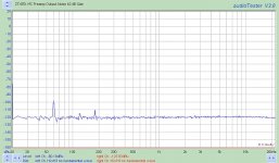
Edit: Linear Audio Silent Switcher MkII – diyAudio Store yes it can do +/-24V at 50mA. Measured noise shown on attachment. Dunno how that compares to batteries but good enough for lazy me to baseline this for my phono build.
I'm learning from both of you as I have not had any successful forays into very low noise designs before (and Gerhard if he's listening).
Edit: Linear Audio Silent Switcher MkII – diyAudio Store yes it can do +/-24V at 50mA. Measured noise shown on attachment. Dunno how that compares to batteries but good enough for lazy me to baseline this for my phono build.
Attachments

Last edited:
I don't read Hans postings as patronising FWIW. You two just have different styles. I need to check with Jan if his silentswitcher can go up to +/-24V as would be interesting to see if that was a possible solution.
I'm learning from both of you as I have not had any successful forays into very low noise designs before (and Gerhard if he's listening).
Edit: Linear Audio Silent Switcher MkII – diyAudio Store yes it can do +/-24V at 50mA. Measured noise shown on attachment. Dunno how that compares to batteries but good enough for lazy me to baseline this for my phono build.
Bill, I'm feeding my MA from an Agilent 6627. It is probably one of the lowest noise lab power supply ever built, and all 4 channels are fully floating. I don't think a silent switcher or anything of that kind will provide a better solution, short of batteries.
My MA has also it's own on board regulators, built with the TI TPS7A47/TPS7A33 RF regulators (the same are used in the Silent Switcher, check out the noise performance on the TI site), and the gain stages have their own PSRR of better than 50dB (uses an active load for the low noise JFET input stage). I can't imagine anything that would be more mains harmonics protected, and because I'm talking about the MA with the input shorted there are no ground loops involved. And the mains harmonic becomes 5x worse if I connect a 30cm shielded cable (and shorted at the end) to the MA input.
This looks, walks and quacks like a radiation (magnetic field) problem, due to the position of my lab in the proximity of the house 200 amps electric panel. But I guess only trying batteries could tell, which I'm trying to avoid (to start with) although I may not have an alternative. I could move the power supply, spectrum analyzer, MA and computer upstairs, but that's some heavy lifting to do (only the 6627 has about 30 kilos, and it's at the bottom of an 150 kilos stack of other equipment) and I'm no spring chicken anymore.
BTW, my problem with the mains harmionics has nothing to do with the real life, it's strictly a lab measurement environment quirk. In real life, the cartridge and it's wiring are collecting orders of magnitude more hum than the 2nV input equivalent of 60Hz I get in my MA (that is, 2uV at the MA output).
Last edited:
For the life of me, I can't get results without annoying 50 Hz & harmonics here.
Maybe if I moved everything out into the garden. I have built a box with an isolation transformer, heavily filtered and without protective earth on the secondary. I use that for the 54846B scope and the HP3325B function generator. That helps somewhat for time-domain measurements.
I do my spectrum measurements mostly with batteries. Both the DUT and the preamp have built-in batteries, and I put both of them into an aluminium cargo box that has only 4 BNC-BNC feedthoughs. That enforces an equipotential GND for the few signals that go in/out. Probably I could improve that cargo box with finger stock on the lid.
DUT and preamp are in the cargo box, isolated by rubber feet. Usually there is only 1 connection, implemented with SMA connectors and semi-rigid coax cable. I'm a RF guy, so SMA is natural. The semi rigid cable is very short, but when there is any additional connection between the DUT and preamp boxes, even direct box-box contact, the hum pickup gets 10 or 15 dB worse. That is clearly magnetic. The aluminium does not help against this, but I was not hurt enough up to now to buy Mu-metal. Alone that mess with red heat for 2h in a hydrogen environment after bending...
It's also interesting: with a coaxial SMA short on the amplifier input, I see more hum than with a 60 Ohm termination ( 1nV/rtHz). I approximate that 60R with a 12 db SMA attenuator with the other side open. That is maybe a 5mm difference, or the damping??
In the upcoming xmas season I'll watch out for "tin" boxes made from soft iron that they use for Nuremberg Lebkuchen now & then. I was not successful last year. Missed those family boxes.
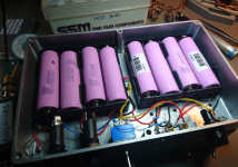
I'm moving now to Lithium batteries. One cell has 3.7V nominally and the best promise sth. like 3Ah. If they promise more, they probably won't work at all. One cell is thus equivalent to 3 NiMH in series. That keeps the number of cells down. The drawback is that the voltage is 4V2 fully charged and may be discharged down to 2V5. I limited myself to 3V5, so I don't get the full stored energy. But once you are down to 3V5, you are quickly down to 2V5, so the loss is not too much. Nevertheless, there is a lot of stored energy. No comparison to NiMH and Pb. I did not have much fun with Pb. Usually empty when I needed them or even sulfated.
I use to bolt two Hammond alu boxes together, one for the amplifier/DUT and one for the batteries, see pic.
The other side is the dual amplifier, in statu nascendi.
Maybe if I moved everything out into the garden. I have built a box with an isolation transformer, heavily filtered and without protective earth on the secondary. I use that for the 54846B scope and the HP3325B function generator. That helps somewhat for time-domain measurements.
I do my spectrum measurements mostly with batteries. Both the DUT and the preamp have built-in batteries, and I put both of them into an aluminium cargo box that has only 4 BNC-BNC feedthoughs. That enforces an equipotential GND for the few signals that go in/out. Probably I could improve that cargo box with finger stock on the lid.
DUT and preamp are in the cargo box, isolated by rubber feet. Usually there is only 1 connection, implemented with SMA connectors and semi-rigid coax cable. I'm a RF guy, so SMA is natural. The semi rigid cable is very short, but when there is any additional connection between the DUT and preamp boxes, even direct box-box contact, the hum pickup gets 10 or 15 dB worse. That is clearly magnetic. The aluminium does not help against this, but I was not hurt enough up to now to buy Mu-metal. Alone that mess with red heat for 2h in a hydrogen environment after bending...
It's also interesting: with a coaxial SMA short on the amplifier input, I see more hum than with a 60 Ohm termination ( 1nV/rtHz). I approximate that 60R with a 12 db SMA attenuator with the other side open. That is maybe a 5mm difference, or the damping??
In the upcoming xmas season I'll watch out for "tin" boxes made from soft iron that they use for Nuremberg Lebkuchen now & then. I was not successful last year. Missed those family boxes.
I'm moving now to Lithium batteries. One cell has 3.7V nominally and the best promise sth. like 3Ah. If they promise more, they probably won't work at all. One cell is thus equivalent to 3 NiMH in series. That keeps the number of cells down. The drawback is that the voltage is 4V2 fully charged and may be discharged down to 2V5. I limited myself to 3V5, so I don't get the full stored energy. But once you are down to 3V5, you are quickly down to 2V5, so the loss is not too much. Nevertheless, there is a lot of stored energy. No comparison to NiMH and Pb. I did not have much fun with Pb. Usually empty when I needed them or even sulfated.
I use to bolt two Hammond alu boxes together, one for the amplifier/DUT and one for the batteries, see pic.
The other side is the dual amplifier, in statu nascendi.
Attachments
Last edited:
I have been in a shielded room at the PTB in Berlin. Large enough to have a party there
in. I was told they use it to measure brain currents without contact. Many levels of Mu metal, I want that also!
One of the quietest places on earth.
in. I was told they use it to measure brain currents without contact. Many levels of Mu metal, I want that also!
One of the quietest places on earth.
Last edited:
For the life of me, I can't get results without annoying 50 Hz & harmonics here.
Maybe if I moved everything out into the garden.
I have been in a shielded room at the PTB in Berlin. Large enough to have a party therein.
What you guys are doing here, pushing the envelope, developing techniques, gaining ground, is astonishing and useful. Thank you for your continued efforts!
However, if you can't get this stuff to operate in a regular dude's living room connected to a regular turntable...
Maybe I am just being impatient, looking too far ahead. Nevermind, carry on.
If you look what Hans has done in his setup you will see that
- there are no loops for induced hum signals in the shields or housings (as per Gerhard's example when connecting DUT with MA with a short coax and in addition the boxes touch et voila, hum currents are induced into this small ground loop where the coax shield resistance creates a signal)
- there is no common path for signal ground signals and shields
And he is going differential all the way down from signal source to main amplifier with the result, that there is no signal ground current. As soon as the hum curents in the shields get mixed with signal currents you get them mixed. This is always the case when using coax cables (or single wire cabels with a shield as do 99% of all RCA interconnects) in a SE configuration as the shielding is used as a shield and the signal ground path in common.
And there are two main sources for such hum signals:
- electrical fields from house installations (50/60 Hz fields are everywhere, e.g. a human body when isolated from ground can develop more than 50V AC potentials due to such fields)
- mains power supplies: these have always a stray capacitance from the live line to the secondary side introducing a huge common mode hum signal. And especially small SMPS suffer from very high capacitance - some more, some less (Hans used 5 Watt types which were good and a 10 Watt type which introduced significant hum signals)
This power supply induced noise can be eliminated when going with floating battery supplies, but this is no guarantee for a hum free system as long as the grounding and shielding layout is not optimal.
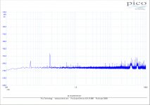
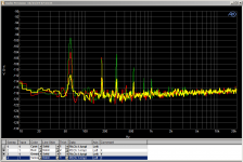
For what it's worth, here the noise spectrum of my MA when powered with a +/-24V SMPS, taken under exactly the same conditions as before:
fs=2MHz, bin width 0.93Hz, output to scope with a 50R Coax.
Input now short circuited instead of being steered from the HA with an Rout=22R through a 60cm RCA cable !
Gain setting on the scope the same 90+34dB to make the level comparable with the spectrum in #1549.
Inside the MA there are 2 Jung-Didden regulators bringing the level to +/-18Volt, but nevertheless, the spectrum is a far cry from the Battery fed version.
Hans
.
Attachments
Most probably, the SMPS creates a common mode hum signal on the power supply ground line. This ground is going into the MA and from there over the coax cable shield to the scope / spectrum analyzer. The resulting hum current creates the signal visible in the spectrum. This signal is independant from the regulators used - they do exactly what they should do by keeping V+ and V- rock solid referenced to the ground line. But it is the ground line which causes the hum problem. As soon as the amp is battery suplied, no hum current coming from mains is injected into the ground line and the resulting spectra are hum free.
I have been following this thread and hoping to find a little input that is a laymans decription of the design intent.
There is a lot of Math being focused on, so I am taking it that the finished performance is a ongoing work in hand, with a few avenues of thought on the math to produce a level that is required to create a working end product.
Is there any explanations available to be offered to the inexperienced,
outlining the advantages of a design like this over the usually available designs.
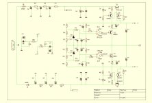
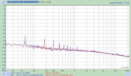
Here is battery powered Groner preamp with shorted input in Hammond box. Input devices LSK170Ax8. Output of the amp is connected to AP with balanced cable. Measurements done in three positions of the box, along X,Y and Z axis. Input ckt (with decoupling large cap) works as a magnetic field sensor.For the life of me, I can't get results without annoying 50 Hz & harmonics here.
Attachments
For the life of me, I can't get results without annoying 50 Hz & harmonics here.
Welcome to the club.
As a comparison point here are a couple of plots from the Flat MC amp I am currently building as my baseline. Once built it will be going to Hans for him to measure and compare. Parking the fact that 60dB of gain is frowned up my many pre-RIAA this shows the noise with a 10R termination and a real MC cartridge. This infers that the cartridge picks up more than the box anyway and is the limiting factor.
These measurements were taken in a fairly hostile magfield (UPS nearby) So will be interesting to see how Hans gets on.
These measurements were taken in a fairly hostile magfield (UPS nearby) So will be interesting to see how Hans gets on.
Attachments
I thought that you are located in the UK and the UK has 50 Hz mains frequency - your plots look like a perfect 60 Hz environment.
How that? Is the heavy UPS running at 60Hz?
How that? Is the heavy UPS running at 60Hz?
These are measurements taken in Dallas. I haven't got a suitable setup to measure this yet. That is my next challenge.
Here is battery powered Groner preamp with shorted input in Hammond box. Input devices LSK170Ax8. Output of the amp is connected to AP with balanced cable. Measurements done in three positions of the box, along X,Y and Z axis. Input ckt (with decoupling large cap) works as a magnetic field sensor.
This is a good example for what I wrote a couple of posts ago.
Battery power is no guarantee for hum free systems. The amp in this case is build with a large (and slotted) groundplane. The battery wiring forms nice loop antennas and the resulting hum currents flow in a somewhat uncontrolled manner through the ground plane were they perfectly mix with the amp signal ground. As even a massive ground plane has some resistance, it creates hum voltages that appear as signal at the output. Ground planes are good for RF but not as good for lowest noise LF amps as they do not allow you to control where exactly currents are flowing
- Home
- Source & Line
- Analogue Source
- Richard Lee's Ultra low Noise MC Head Amp