That one looks very nice.
Quite a lot more parts that I imagined, but interesting.
It's designed with both "constant power" and "current drive" concepts in mind.
Here are the prototype tests, performed by Thimios: VHex+CP measurements
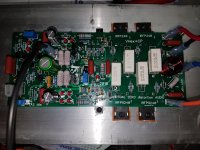
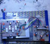
Attached is what our through-hole board looks like.
Attachments
Not exactly. I was referring to something like this.
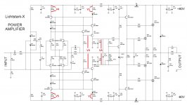
The base to collector connection on Q6 should be on Q5, that diagram blows up as drawn.
The base to collector connection on Q6 should be on Q5, that diagram blows up as drawn.
Yep - mistake in the book 🙂
Q6, Q9 will be dead right away 😱
Attached is what our through-hole board looks like.
There's no way I can fit five of those boards inside the Onkyo receiver to replace the existing amps. No SMD for me either.
That's why I specifically mentioned the Goldmund.
The layout can be redesigned in more convenient shape.
We use specifically wide traces in the OPS section - if you make them sort of equal to the ones used in Onkyo - the board will be much smaller.
Why do you think Goldmund is more compact? Proper implementation would require the same kind of board size.
Why no SMD? 🙄
Why don't you like the "classic" VHex+ - its front-end has got much less components, being a truly top performer. You probably don't see its advantages right away, but that circuit utilizes a few cool ideas, making it rather unique.
I am laying out a board that will fit into a Pioneer sx780 as this will be used there.
It is very compact as both channels fit onto an express PCB cheap miniboard layout
It will be compared to my opa134 based amp in my Sx3700
It is very compact as both channels fit onto an express PCB cheap miniboard layout
It will be compared to my opa134 based amp in my Sx3700
Last edited:
Hello vzaichenko
greetings looking at picture in #2002 22 ohms is 1 watt supply resistors
feeding ips section
warm regards
Andrew
greetings looking at picture in #2002 22 ohms is 1 watt supply resistors
feeding ips section
warm regards
Andrew
Hello vzaichenko
greetings looking at picture in #2002 22 ohms is 1 watt supply resistors
feeding ips section
warm regards
Andrew
That"s right - those 22 ohm resistors at the rails are 1W.
Hi Valery, their two mistake on screen VHex OPS (2P and 3P). Take a look at ND/V- and PD/V+ marking they are reversed....
Marc
Marc
Lichtstark V 1.O
Hello vzaichenko
greetings i just did a test with 30 volts dc +/- amp came on
without any problems but t😉 he led did not come on feeding it
with signal from cd player sound clarity is very detailed can
you help me with biasing it with 57 volts dc +/-
warm regards
Andrew
Hello vzaichenko
greetings i just did a test with 30 volts dc +/- amp came on
without any problems but t😉 he led did not come on feeding it
with signal from cd player sound clarity is very detailed can
you help me with biasing it with 57 volts dc +/-
warm regards
Andrew
Attachments
Hi Valery, their two mistake on screen VHex OPS (2P and 3P). Take a look at ND/V- and PD/V+ marking they are reversed....
Marc
Right - thank you Marc, it actually came from schematic (although it looks fine there). I have corrected it in my files.
To All - this is just the screen mistake - all connections are fine.
Last edited:
Hello vzaichenko
greetings i just did a test with 30 volts dc +/- amp came on
without any problems but t😉 he led did not come on feeding it
with signal from cd player sound clarity is very detailed can
you help me with biasing it with 57 volts dc +/-
warm regards
Andrew
Hi Andrew,
Let's check the currents in the IPS module first.
Can you please measure the voltages as shown on the schematic.
Then just put them in the post like:
V1 = ...
V2 = ...
etc.
Cheers,
Valery
Attachments
Last edited:
Valery, if you reverse D15 and R20 as well as their conterparts and then connect the collector of Q32 the anode of D15, is there a difference. The layout becomes easier if this connection is made. this wil bypass the 100 ohm resistor in the path of Q32 ( and Q15)
It also seems possible to omit C1 and use the offset trim to compensate for it
It also seems possible to omit C1 and use the offset trim to compensate for it
Last edited:
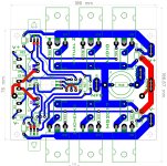
Layout tryout on Valery VHex_OPS. The board mesure 100x76mm with 3P. So it has some 1P/2P/3P universal layout as there is no gain to go for 2P or 1P layout. Price will be the same. board house will coast you under 30$ (shipping included) for 10u
Marc
Marc
Attachments


Last edited:
Layout tryout on Valery VHex_OPS. The board mesure 100x76mm with 3P. So it has some 1P/2P/3P universal layout as there is no gain to go for 2P or 1P layout. Price will be the same. board house will coast you under 30$ (shipping included) for 10u
Marc
Thank you Marc - fantastic job! Universal board for OPS 😎
Valery, if you reverse D15 and R20 as well as their conterparts and then connect the collector of Q32 the anode of D15, is there a difference. The layout becomes easier if this connection is made. this wil bypass the 100 ohm resistor in the path of Q32 ( and Q15)
It also seems possible to omit C1 and use the offset trim to compensate for it
Unfortunately - there is a difference.
C1 - yes, possible. I leave a placeholder in place anyway - then one can use the cap or jumper the placeholder 😉
Valery - Thanks for the response.
I breadboarded it and found the difference as well. Dumb Mistake
the current from Q32 (~2ma ) causes an extra .2v across the 100 ohm resistor greatly effecting current through the diff stage. I am changing my layout.
Cheers
I breadboarded it and found the difference as well. Dumb Mistake
the current from Q32 (~2ma ) causes an extra .2v across the 100 ohm resistor greatly effecting current through the diff stage. I am changing my layout.
Cheers
Last edited:
Layout tryout on Valery VHex_OPS. The board mesure 100x76mm with 3P. So it has some 1P/2P/3P universal layout as there is no gain to go for 2P or 1P layout. Price will be the same. board house will coast you under 30$ (shipping included) for 10u
Marc
Kewl job, Marc
 !
!My personal favourite were a board that combines both the Lichtstark IPS and the VHEX OPS, though. Maybe in the format of the Honey Badger board? I surely prefer this in-line arrangement of the driver and power devices, as this allows for slim enclosures.
Best regards!
This design alow you to use 3U heatsink. With 3P Output slim case as 2U (80mm high heatsink) i don't know if there is enough headroom for cooling.
I will try to reduce LS-IP in same shape as the OPS above
Marc
I will try to reduce LS-IP in same shape as the OPS above
Marc
- Home
- Amplifiers
- Solid State
- Revisiting some "old" ideas from 1970's - IPS, OPS