Is anyone in Canada going to order the Lichtstark_v1.0 pcbs from pcbway? We can share on an order. I would like a couple of them to play with. I do not need 10 of them.
I'll be getting VHex version boards and inputs for the modular series. If there's any intrest for the three pair universal mount version I'll get some of them too.
I will need a OPS, so I can go with VHex. Which one is Vhex in the index list?
I am not sure what the modular series is, I have to look that up, I have not been following along very well. Index# pls
I am not sure what the modular series is, I have to look that up, I have not been following along very well. Index# pls
Last edited:
I've layed out Valery's non switching output stage in a left and right channel fomat and a plate amp format to accept plug in input boards. That's our modular series. The latest versions have built in dc detection, solid state speaker relays and temp sensors that connect to our 21st century control boards.
You guys have so many on the go, sorry I am confused 🙂 I dislike this web site, it is so hard to organize each design, no fault of you guys, I asked Mooly to figure out a way to organize, but they want to leave it the way it as is.
Virtual Zero Audio - power amplifier products Valery has been updating the first post in the thread with an index for new designs too.
Last edited:
I want to say thank you to everyone contributing in this thread, just one suggestion
is to start a new thread for example on Hot Air Soldering, it is actually something I'd
like to find in the future since I have no experience doing it DIY. We had a fab shop
at all my jobs with large companies and I didn't even get a look at how it was done.
Thanks again, lots of great info.
is to start a new thread for example on Hot Air Soldering, it is actually something I'd
like to find in the future since I have no experience doing it DIY. We had a fab shop
at all my jobs with large companies and I didn't even get a look at how it was done.
Thanks again, lots of great info.
I want to say thank you to everyone contributing in this thread, just one suggestion
is to start a new thread for example on Hot Air Soldering, it is actually something I'd
like to find in the future since I have no experience doing it DIY. We had a fab shop
at all my jobs with large companies and I didn't even get a look at how it was done.
Thanks again, lots of great info.
Probably the best source of info on these forms of soldering is YouTube. It's easier to figure things out by watching what they are doing. Probably the biggest hurdle to overcome is the fear of burning parts. Contrary to conventional wisdom, parts don't self destruct when they get hot (with no power applied to them). SMT ICs are very robust and can be rebaked numerous times with no issues. Resistors and capacitors are more likely to be damaged from heat (the rapid cooling after actually), but Ricks method with two irons works great.
Thanks, I'm not doing any of this work at the moment but might try some down the road
and will keep those tips in mind.
and will keep those tips in mind.
Eagerly waiting for the first Lichtstark reviews...!
And here is a cool method for DIY solder paste stenciling:
https://www.youtube.com/watch?v=JWUJtmgh55M
And here is a cool method for DIY solder paste stenciling:
https://www.youtube.com/watch?v=JWUJtmgh55M
Here's his new way of etching stencils. https://www.youtube.com/watch?annot...&feature=iv&src_vid=JWUJtmgh55M&v=zyB-01p7AtI I think laser etching Mylar is easier.
Christos Anesti - Happy Easter to all.
Alithos Anesti! All the best for Easter!
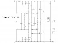
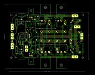
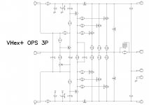
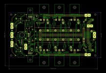
VHex+ 2P OPS and VHex+ 3P OPS modules
Hi Andrew and All,
Please see the good-matching OPS section documents attaches - 2-pairs and 3-pairs OPS options.
Optimal rails for 2-pairs OPS = +/-50...60V DC
Optimal rails for 3-pairs OPS = +/-65...75V DC
NOTE! Different rails require some resistors'value adjustment in Lichtstark front-end module!!! Let me know the rails you are going to use - I will let you know the values.
No changes in the OPS though.
Also note! Connectors on Lichtstark IPS and VHex OPS modules are mirrored with regards to each other! If they are placed one next to the other, IPS module has to be mounted either upside-down, or 90 degrees.
Cheers,
Valery
Hello vaizchenko
greetings can you share pcb output section trying to make
your design
warm regards
Andrew😉
Hi Andrew and All,
Please see the good-matching OPS section documents attaches - 2-pairs and 3-pairs OPS options.
Optimal rails for 2-pairs OPS = +/-50...60V DC
Optimal rails for 3-pairs OPS = +/-65...75V DC
NOTE! Different rails require some resistors'value adjustment in Lichtstark front-end module!!! Let me know the rails you are going to use - I will let you know the values.
No changes in the OPS though.
Also note! Connectors on Lichtstark IPS and VHex OPS modules are mirrored with regards to each other! If they are placed one next to the other, IPS module has to be mounted either upside-down, or 90 degrees.
Cheers,
Valery
Attachments
-
 00-VHex-OPS-2P-Sch.JPG90 KB · Views: 447
 -
 00-VHex-OPS-2P-Screen.JPG158.8 KB · Views: 443
 -
 00-VHex-OPS-3P-Sch.JPG101 KB · Views: 414
 -
 00-VHex-OPS-3P-Screen.JPG182.9 KB · Views: 405
 -
OPS-2P-Gerber.zip48.4 KB · Views: 127
-
VHex-OPS-3P-Screen.pdf47.5 KB · Views: 158
-
VHex-OPS-3P-Sch.pdf31.5 KB · Views: 162
-
VHex-OPS-2P-Screen.pdf42 KB · Views: 148
-
VHex-OPS-2P-Sch.pdf27.9 KB · Views: 156
-
OPS-3P-Gerber.zip51.9 KB · Views: 130
Hi Valery,
with these output FETs, Q10, the Vbe multiplier transistor, doesn't need to be attached to the heat sink?
Best regards!
with these output FETs, Q10, the Vbe multiplier transistor, doesn't need to be attached to the heat sink?
Best regards!
Hi Valery,
versions for etching would be interesting for me.
I have another question about the supply voltage.
You wrote for 2 Pairs 60V DC is the max.
How can I calculate this?
My consideration about this:
The max. current of the IRFP240 is 12A at 100°C.
R=U/I=60V/(2*12A)=2,5Ohm
So the mimum load will be 2,5Ohm.
The complex load of a 4Ohm speaker can be smaller than 4 Ohm, but 2,5 Ohm should be ok.
Are my considerations right?
Hi Valery,
with these output FETs, Q10, the Vbe multiplier transistor, doesn't need to be attached to the heat sink?
Best regards!
Hi Kay,
You would not need to attach Q10 to the heatsink if those FETs would be laterals.
However, IRFP240/9240 are HexFETs - their temperature coefficient is close to BJTs' one - slightly lower, but still - Q10 must be placed on the heatsink under the board (there's a hole in the board for a screw). Otherwise, thermal runaway will be the case.
Cheers,
Valery
Hi Valery,
I loaded those gerbers/drills, for the VHEX designs, they look fine to me upon a first glance.
In the schematic I see R symbols, some "<" and some ">" 🙂 I assume that they are rotated 180, you did not have them in your legend that you supplied the other day, what are those wattages? I assume Russia has an equivalent of ANSI or IEC?
Mouser has these
0.22/3W 660-MOSX3CT631RR22J for $0.288CDN and
0.22/5W 660-MOSX5CR22J for $1.34CDN
For those diodes, 1N4004, is it not best for them to be a fast recovery type? something like UF4004 and is a 1A diode sufficient in size for the o/p stage back emf clamp diode?
Thanks
Rick
Last edited:
- Home
- Amplifiers
- Solid State
- Revisiting some "old" ideas from 1970's - IPS, OPS