Hi Terry,
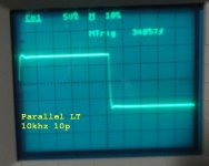
If you increase C7 value from 2.2pF to 10pF - that will eliminate the overshoot.
Cheers,
Valery
10p added an over shoot to the top.
Attachments
10p added an over shoot to the top.
Let's make it 22pF - it has to show the rounded corners.
OK I changed it to 22p. They are a bit rounded now. I don't have time take pictures right now. I will try 15p next and see how that looks later when I get home. I'll post pics then. I'll get a shot of it clipping too.
OK I changed it to 22p. They are a bit rounded now. I don't have time take pictures right now. I will try 15p next and see how that looks later when I get home. I'll post pics then. I'll get a shot of it clipping too.
Hi Terry!
Ok, we're almost there.
What you can also do for the best performance:
- Increase R5, R12 from 22R to 47R (this will "calm down" the LTP a little bit);
- Add 220pF capacitor in parallel with R15 (18K);
- After that play with C7 value - I believe, 15p is about the optimal one.
Many thanks,
Valery
Terry - one more thing, if you don't mind.
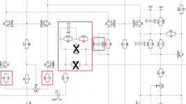
Remove C7, R14 and place the network C21, R32, R35 instead.
I have marked all the amendments on the picture attached with red frames.
In the end you can play with C21 value for the best square wave at the output.
Cheers,
Valery
Remove C7, R14 and place the network C21, R32, R35 instead.
I have marked all the amendments on the picture attached with red frames.
In the end you can play with C21 value for the best square wave at the output.
Cheers,
Valery
Attachments
Terry - one more thing, if you don't mind.
Remove C7, R14 and place the network C21, R32, R35 instead.
I have marked all the amendments on the picture attached with red frames.
In the end you can play with C21 value for the best square wave at the output.
Cheers,
Valery
Hi Valery,
Sorry, I've been lazy today. Sitting around watching the Olympics I have recorded. 😱
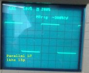
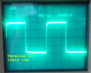
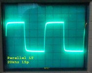
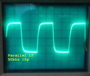
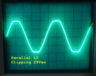
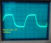
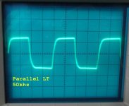
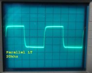
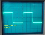
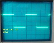
I made the changes you suggested. I actually think the square waves are a little more rounded then they were with just the 22p. I said I would show it clipping but the gain must be low because I can only get the output to 20Vac and that is not enough to make it clip. My sine wave generator only produces 1.5Vac. Here are some scope shots of some square waves.
Attachments
Terry, thanks a lot - looks good to me.
In fact, in this "NFB network" setup, C21 can be reduced to 10pF for the best sqr wave response. Anyway, that's a matter of the minor tune-up now.
Did you try to audition it by chance?
In fact, in this "NFB network" setup, C21 can be reduced to 10pF for the best sqr wave response. Anyway, that's a matter of the minor tune-up now.
Did you try to audition it by chance?
Hi Valery.
I only played music through it for a couple of minutes just to make sure I wasn't hearing anything that shouldn't be there. Like I said, it is very low gain. I wanted to get this channel working at its best before I rework the second channel. Then I will but them both through my good speakers and give it a closer listen.
I only played music through it for a couple of minutes just to make sure I wasn't hearing anything that shouldn't be there. Like I said, it is very low gain. I wanted to get this channel working at its best before I rework the second channel. Then I will but them both through my good speakers and give it a closer listen.
Low gain is strange. Maybe some R value is incorrect in the feedback?
Desired gain is 29db = 28 times = (R32 + R35) / R13 + 1 = (15K + 12K) / 1K + 1; as per post #1005 schematic above.
Desired gain is 29db = 28 times = (R32 + R35) / R13 + 1 = (15K + 12K) / 1K + 1; as per post #1005 schematic above.
I will measure again in the morning. I know i put 1.5vac in and measured 22vac out. I will recheck everything. I have a stand alone CDrom that I use for quick testing. I had it up full and it wasn't very loud so I know what I'm measuring is likely true. I will compare it to the other channel as well. That one is unmodified. I'll get back to you.
I found my mistake. I forgot to pull R14. I will get some scope shots up in an hour or so. I will go ahead and change the other channel too so I can give some listening impressions.
Sorry for the confusion.
Sorry for the confusion.
OK I have all the values changed to the values in post #1005. Attached are some scope shots. One issue is the offset. The trimmer is at its limit and I still have 6mV on one channel and 30mv on the other. I did match hfe on all 4 of the LTP transistors.
Attachments
I see - then, in the final version I will make R5, R12 = 22R again, but use 50R trimmer - that will add more trimming range.
When I get a little time I will make those changes and get back to you. I did listen to 4 or 5 songs through it. Sounds good. It has a pretty nasty turn-on sound. Offset is a little high at initial switch on. A good candidate for speaker protection.
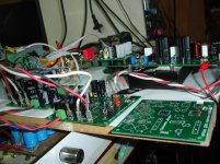
A new package arrived today!
Thanks Evan!
Thanks Evan!
Attachments
Last edited:

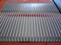
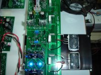
An early test
Waiting for the heatshink package i had tried an early test.
Nothing special,just i can't resist giving a first listening test.
Excellent sound,deep bass,fine treble very musical....just Excellent!
It is the first time that listening test take place first, before scopes and the measurements!
Waiting for the heatshink package i had tried an early test.
Nothing special,just i can't resist giving a first listening test.
Excellent sound,deep bass,fine treble very musical....just Excellent!
It is the first time that listening test take place first, before scopes and the measurements!
Attachments
Last edited:

- Home
- Amplifiers
- Solid State
- Revisiting some "old" ideas from 1970's - IPS, OPS