I don't think so because signal- connected directly to the case this way.What is with the rca plugs? Are those meant to mount in the rear panel somehow?
What is with the rca plugs? Are those meant to mount in the rear panel somehow?
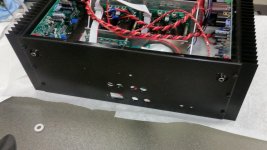
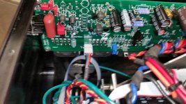
Terry, yes - see the pictures. This is an earlier integrated IPS-OPS version, but overall idea is the same - the board is placed in a way that the plug appears on the rear panel.
Advantage - no input wires - less noise/hum.
Disadvantage - we have to design the separate layouts for left and right channels. However, we believe it makes sense, bearing in mind the advantage 🙂
Now, with the new modular design, we can change the front-end section without touching the bulky OPS board - very convenient!
Front-ends are inexpensive, so the amp owner can try different voltage amplification topologies and choose the one he likes better 😎
Attachments
I don't think so because signal- connected directly to the case this way.
We make a bigger hole and isolate the signal ground from the case.
do you mean holes for the resistor leads?
0.6mm or 0.8mm?
The idea is to have them smaller on the layout, so that you can better center the drill, pointing a small spot on the etched board. Then you drill the holes as big as required, drilling also the copper pad.
You can use a piece of board too.We make a bigger hole and isolate the signal ground from the case.
Screw the board to the case and the rca connector to the pice of board.
More durable
Isn't a good idea to stress the rca connector
when this is just soldered on board.
Last edited:
The connector is designed to mount flat to the rear cover. If you look close, there is a small ring of plastic sticking out on the mounting surface. This centers it in the hole and adds insulation. There is also a mounting screw hole there. The flat metal surface is chassis grounded, and is not connected to the RCA ground.
Another set of heatsinks are on their way to Thimios. Heatsink USA said that when they typed the zip code the address label must have auto-filled to France. Without me asking they were already getting another set together to send to Greece. They most likely will be out the cost of the initial product and shipping. I was happy they admitted the mistake and took steps to remedy the situation without any pressure. Well done.
Evan
Evan
I will be happy with this mistakeAnother set of heatsinks are on their way to Thimios. Heatsink USA said that when they typed the zip code the address label must have auto-filled to France. Without me asking they were already getting another set together to send to Greece. They most likely will be out the cost of the initial product and shipping. I was happy they admitted the mistake and took steps to remedy the situation without any pressure. Well done.
Evan
Sorry, I got side tracked today. I'm planning to finish the Parallel-LT tomorrow. What is the planned Rail voltage for this single pair version. Seems maybe I can get by with less than 100V caps. I'm running low on the 100UF 100V caps. If I can go with 63V it would help.
Thanks, Terry
Thanks, Terry
Sorry, I got side tracked today. I'm planning to finish the Parallel-LT tomorrow. What is the planned Rail voltage for this single pair version. Seems maybe I can get by with less than 100V caps. I'm running low on the 100UF 100V caps. If I can go with 63V it would help.
Thanks, Terry
Hi Terry,
What PSU options have you got available?
Initially, it was designed for +/-50V with 2 pairs.
If you'd like to go lower - let me know exact voltage, I will chech if some R values need to be adjusted.
Cheers,
Valery
I have a few options and a variac. That is why I am asking you what voltage you had intended. I'm using your layout with one pair. I guess my point is that even with 50v rails, 100v caps aren't needed are they? Just looking at my options. I am trying to build it out of my parts bins. So, what rail voltage would you suggest for this single pair circuit?
Thanks, Terry
Thanks, Terry
OK, then let's test at +/-50V (not using the load below 8 ohm).
For most of the caps, including all electrolytics, 63V rating is fine. However, C16, C17 (47pF) may see rail-to-rail voltage at high swing (well, 100V will be fine for a test).
For most of the caps, including all electrolytics, 63V rating is fine. However, C16, C17 (47pF) may see rail-to-rail voltage at high swing (well, 100V will be fine for a test).
Right, Terry - I will look at it closer in the evening, but for now you can just solder 11K in parallel with R25 - that will give you 1K in total. Or 10K in parallel - then total value will be 990R, which is going to be still ok.
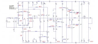
Ok I have been two days trying to find an error in my work but can't. I checked every part for correctness and as far as I can tell I have everything as per layout drawing. I'm assuming that the TO-126 and TO-220 parts all have the base pin marked with a square pad. I have done my best to check out the layout but I must be missing something. I'm attaching a schematic with voltages. Any help will be appreciated.
Blessings, Terry
Blessings, Terry
Attachments
I didn't change anything. They are per schematic in post 947.
http://www.diyaudio.com/forums/soli...e-old-ideas-1970s-ips-ops-19.html#post4795682
http://www.diyaudio.com/forums/soli...e-old-ideas-1970s-ips-ops-19.html#post4795682
- Home
- Amplifiers
- Solid State
- Revisiting some "old" ideas from 1970's - IPS, OPS