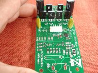
Exactly!They are easy to solder, but hard to see the orientation marking.

Some electrolytic don't fit.
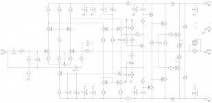
Are you sure for these C4,C7= 470uf/25v?
Last edited:
Ok,i will post tomorrow,i haven't the board with me now.Can you post a picture? I'm not in my office, so I'm not able to look at my boards.
Thanks.
Here is.
One that fit perfect is 100uf/25V
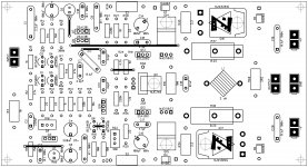
Other questions,is it necessary a heatsink for these 1381,3503 tran.for +/-50v power supply?
What is the values for R19 R21,C11,C14?
One that fit perfect is 100uf/25V
Other questions,is it necessary a heatsink for these 1381,3503 tran.for +/-50v power supply?
What is the values for R19 R21,C11,C14?
Attachments
Last edited:
I'm at the office now. I put 220uF there. These are just reservoir caps. They are fed from 1000uF caps in the supply, so the 100uF would likely be fine there.
Thanks Jeff , may be Valery can answer about non value components.I'm at the office now. I put 220uF there. These are just reservoir caps. They are fed from 1000uF caps in the supply, so the 100uF would likely be fine there.
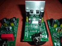
Thanks Jeff,all these are unsoldered, i want to know about heatsink first.You have Q3 - Q6 installed backwards.
If it's necessary putting heatsink,i will mount all on the heatsink and then i will solder all together.
In any case,Please moderators to delete this image to not give troubles to someone.
Last edited:
All 6 need to be on heatsink.
Thanks,can a small heatsink do the work?
Last edited:
Here is.
One that fit perfect is 100uf/25V
Other questions,is it necessary a heatsink for these 1381,3503 tran.for +/-50v power supply?
What is the values for R19 R21,C11,C14?
Hi Thimios,
Back to my PC.
100uF/25V will be fine - those are just local decoupling, the placeholders appeared to be smallish for 470uF.
R19 R21,C11,C14 - leave them unsoldered for the time being - they are reserved for nested feedback options.
Local heatsinks or aluminium plates are required for all the TO-126 transistors - they can be rather small, but they need to be there, just to allow some heat dissipation, ensuring stable VAS operating points.
All looks good so far!
Cheers,
Valery
That'll be fine.
Yep - more than enough.
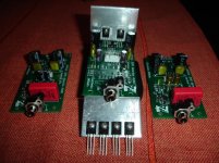
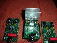
Thanks,at least one channel from this vz-x4 is complete.The other channel must be wait due to missing parts.
To all guys who didn't tried yet the smd montaz.
This is an easy process.
You must have a good solder iron,good quality thin solder wire and some experience.
More easy and faster than thru hole!
Try it!
Last edited:
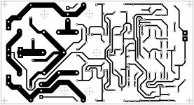
Parallel-LT - single side layout for etching
Continuing on the design, presented in Post #821, I have developed a diy-friendly layout of the "lite" version of Parallel amplifier (single output pair).
I can't test it myself - my lab is disassembled again - so, if somebody wants to try this cool creature - that would be great!
Nominal rails are +/-50V DC.
Cheers,
Valery
Attachments
- Home
- Amplifiers
- Solid State
- Revisiting some "old" ideas from 1970's - IPS, OPS