Today i have test the Kypton v IPS whose servo is the same with Symasui.
What i found?
Kypton v start normaly with an offset about 400mv and fast go to 0v.
Symasui with servo never touch the 0v,always start from 3v and ended at 2.9mV.(same offset as in the non servo version).
Kypton v servo gnd is at the signal gnd,when Symasui servo gnd is at the power gnd.
Here is a commercial solution.

Thimios, you're right - I deliberately was asking if there is some voltage difference between the signal ground and the power ground - I think, this is the reason for such a nasty behavior of Symasui with servo.
Same as the global NFB network, servo needs to be referenced to signal ground - as we see in Kypton-V.
No Valery it isn't the signal gnd or power gnd,it is more complex.Thimios, you're right - I deliberately was asking if there is some voltage difference between the signal ground and the power ground - I think, this is the reason for such a nasty behavior of Symasui with servo.
Same as the global NFB network, servo needs to be referenced to signal ground - as we see in Kypton-V.
I will come back soon with details.
Today i have test the Kypton v IPS whose servo is the same with Symasui.
What i found?
diyAudio
Kypton v start normaly with an offset about 400mv and fast go to 0v.
Symasui with servo never touch the 0v,always start from 3v and ended at 2.9mV.(same offset as in the non servo version).
Kypton v servo gnd is at the signal gnd,when Symasui servo gnd is at the power gnd.
Here is a commercial solution.
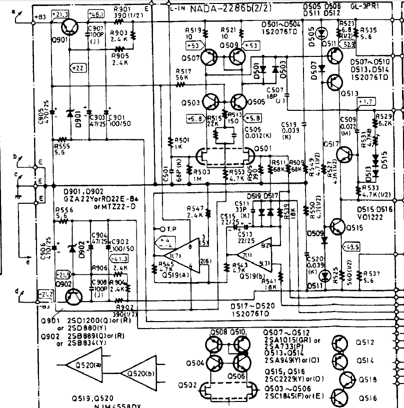
That's what I'm talking about here: http://www.diyaudio.com/forums/solid-state/290970-several-schemes-9.html#post4868898.
As we can see, the output 5(3) of opamp Q519(b) goes outside the scheme, while the need to connect to ground and this connection would be a draw much easier and closer. We need to see the whole scheme, but I think this wire is or goes to another amplifier, measuring a voltage drop on the cable between the blocks of the amplifiers to reduce interference, or the Mecca of ground, or "cool" terminal on the speakers.
Engineers from the firm Onkyo were able to come up with such things.
Upd.
Here are the manual amplifier M-504. The wire you were asking about, connected to "cold" (-) terminal of speaker systems (wire SV from R231 22k, square A3). If you choose the wire resistance between the connection =point SV and Mecca ground= 2 times more resistance than cable acoustic systems, the resistance of the speaker cable will be compensated by the unit of opamp Q203.
Attachments
Last edited:
Today i have test the Kypton v IPS whose servo is the same with Symasui.
What i found?
Kypton v start normaly with an offset about 400mv and fast go to 0v.
Symasui with servo never touch the 0v,always start from 3v and ended at 2.9mV.(same offset as in the non servo version).
Kypton v servo gnd is at the signal gnd,when Symasui servo gnd is at the power gnd.
Here is a commercial solution.
I updated the servo schemes in those. Going with a much lower servo FB
impedance solves any slower settling times.
5.6K from TLxxx output to the NFB node gives <50mS settling and just
boosts global gain by a couple DB.
All the servo'ed creations ... (even my present leach/spooky) clone use
that 5.6k (DC) 22-27K (AC) feedback "mix". Nearly instant DC settling.
Edit - I have the V/symasui/spook - all reference the TLxxx (servo) to the signal ground
(lifted -4.7R). You might have the prototype versions - the PCB house versions are
the same (lifted servo reference).
OS
Last edited:
I thought you'd posted an updated schematic somewhere showing this, but I wasn't able to find it.I updated the servo schemes in those. Going with a much lower servo FB
impedance solves any slower settling times.
5.6K from TLxxx output to the NFB node gives <50mS settling and just
boosts global gain by a couple DB.
All the servo'ed creations ... (even my present leach/spooky) clone use
that 5.6k (DC) 22-27K (AC) feedback "mix". Nearly instant DC settling.
Edit - I have the V/symasui/spook - all reference the TLxxx (servo) to the signal ground
(lifted -4.7R). You might have the prototype versions - the PCB house versions are
the same (lifted servo reference).
OS
That's what I'm talking about here: http://www.diyaudio.com/forums/solid-state/290970-several-schemes-9.html#post4868898.
As we can see, the output 5(3) of opamp Q519(b) goes outside the scheme, while the need to connect to ground and this connection would be a draw much easier and closer. We need to see the whole scheme, but I think this wire is or goes to another amplifier, measuring a voltage drop on the cable between the blocks of the amplifiers to reduce interference, or the Mecca of ground, or "cool" terminal on the speakers.
Engineers from the firm Onkyo were able to come up with such things.
Upd.
Here are the manual amplifier M-504. The wire you were asking about, connected to "cold" (-) terminal of speaker systems (wire SV from R231 22k, square A3). If you choose the wire resistance between the connection =point SV and Mecca ground= 2 times more resistance than cable acoustic systems, the resistance of the speaker cable will be compensated by the unit of opamp Q203.
Actually, this M-504 is a good example of using the right ground references.
DC servo's ground reference is taken right from the "-" terminal (that's where we need DC to be "zero") - SV. Zobel is also connected in a clever way - separate wire goes to the power amp section ground - EP and E are different connections. Nice.
I updated the servo schemes in those. Going with a much lower servo FB
impedance solves any slower settling times.
5.6K from TLxxx output to the NFB node gives <50mS settling and just
boosts global gain by a couple DB.
All the servo'ed creations ... (even my present leach/spooky) clone use
that 5.6k (DC) 22-27K (AC) feedback "mix". Nearly instant DC settling.
Edit - I have the V/symasui/spook - all reference the TLxxx (servo) to the signal ground
(lifted -4.7R). You might have the prototype versions - the PCB house versions are
the same (lifted servo reference).
OS
Pete, thank you for clarification. We had some servo "puzzles" during the tests performed by Thimios here. One of the most interesting ones - offset increase during the constant amplitude signal sweep within some frequency range. Quick sweep to higher frequencies result in short term DC imbalance, before the servo zeroes it out.
Cheers,
Val
Hi boss!I updated the servo schemes in those. Going with a much lower servo FB
impedance solves any slower settling times.
5.6K from TLxxx output to the NFB node gives <50mS settling and just
boosts global gain by a couple DB.
All the servo'ed creations ... (even my present leach/spooky) clone use
that 5.6k (DC) 22-27K (AC) feedback "mix". Nearly instant DC settling.
Edit - I have the V/symasui/spook - all reference the TLxxx (servo) to the signal ground
(lifted -4.7R). You might have the prototype versions - the PCB house versions are
the same (lifted servo reference).
OS
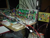
My experience to Valery N.S gives me the opportunity for the two giants mixing!
Testing the Symasui Survivor i see that is some abnormal function on offset controller.
Then i hooked up the Symasui on the Slewmaster and i see the same.
What is the strange?
1)The long settle time (about of 20'').
2)Offset controller can't ended up Below 2.9mV.
To see what happen,the IPS modified as non servo.
This non servo version(tested here.http://www.diyaudio.com/forums/solid-state/248105-slewmaster-cfa-vs-vfa-rumble-957.html) starts immedietly from about 100mV & ENDED UP VERY SOON about 5'' latter at 2,9mV
Then could not resist the challenge for a separate +/-15v power supply for servo and input,this challenge gives 0 v offset!(non servo) that is because of a small difference in + & - voltages.
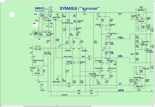
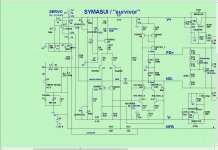
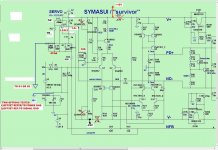
picture 1 is my version as built when the problem existing
picture 2 is what Jeff post as an apdate version.
picture 3 is what i have modify now.
Two days now i have test step by step using ARTA,RMAA and STEPS.
What i see?
1)TL072 don't act well in this IPS as this although the modifications can't go below 2.9mV.
2)LF412 can go to zero ONLY WHEN C12 decreases to 470nf or below.
3)The GND reference of the offset controller haven't measurements results.
4)The settling time is reduced when the value of Ρ28 resistance decreases.
Now about measurements.
I will post 2 different set of measurements.
One using power GND as reference for offset controller and the other using Signal GND as reference.
I believe that the most suitable program for offset testing is the STEPS.
May be someone have a better way to do.
Attachments
Last edited:
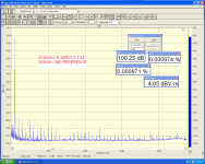
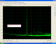
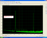
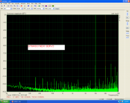
First set using signal gnd as offset reference.
I must say that the output board(power amplifier out)is the Slewmaster.
Reason that i post here is why this adventure has been started here.🙂
I hope that isn't something wrong😕
Sorry i have mixed the STEPS files so i will retest😱
I must say that the output board(power amplifier out)is the Slewmaster.
Reason that i post here is why this adventure has been started here.🙂
I hope that isn't something wrong😕
Sorry i have mixed the STEPS files so i will retest😱
Attachments
-
 SYMASUI SPECTRA.PNG104.8 KB · Views: 143
 -
 NO LOAD 23V SPECTRA OUT.PNG99.9 KB · Views: 146
 -
 NO LOAD 23V OUT.PNG103.4 KB · Views: 127
 -
 LOW LEVEL IMD.PNG104.4 KB · Views: 130
 -
 IMD NEW SERVO SYM.PNG106.8 KB · Views: 125
 -
 20KHZ 1.1.047 SIGN GND.PNG109.2 KB · Views: 144
 -
 10KHZ.PNG111.8 KB · Views: 325
 -
 27V SIG GND.PNG107.9 KB · Views: 328
 -
 DSC08399.jpg340.6 KB · Views: 174
Last edited:
Hi!May be someone have a better way to do.
1. You don't need to rush with the settling time.
2. You picked the wrong servo circuit, see file. It gives large distortion at frequencies around 20 Hz due to the nonlinear conductance of the diode protection D7D8. I am not mistaken, if I make an assumption: you don't need the distortion.
3. You can get rid of these distortions, if you increase the resistance R26-27 and the capacitance C11-13. This increase to reduce the signal voltage to the diodes 7 and 8.
4. But the settling time will also increase, see first paragraph 1. You must make a simple choice: will you accept this increase. or you come to terms with the distortions.
5. The voltage at the amplifier output 3 - 5mV is acceptable, this voltage is too small to worry about him.
6. You need to choose a GND to connect the integrator closest to the signal ground. The Japanese did a similar connection to the ground of acoustic systems for their own reasons. I explained these reasons. You don't have these reasons, another schematic of the servo, so you don't need to do that.
Attachments
Last edited:
Hi!Actually, this M-504 is a good example of using the right ground references.
DC servo's ground reference is taken right from the "-" terminal (that's where we need DC to be "zero") - SV.
Above I explained why Japanese people made it so. You want to repeat it. But if you don't understand the reasons for the decision of the Japanese, you will have to rely more on God, than on circuitry. 🙂
Hi and thanks for reply.Hi!
1. You don't need to rush with the settling time.
2. You picked the wrong servo circuit, see file. It gives large distortion at frequencies around 20 Hz due to the nonlinear conductance of the diode protection D7D8. I am not mistaken, if I make an assumption: you don't need the distortion.
3. You can get rid of these distortions, if you increase the resistance R26-27 and the capacitance C11-13. This increase to reduce the signal voltage to the diodes 7 and 8.
4. But the settling time will also increase, see first paragraph 1. You must make a simple choice: will you accept this increase. or you come to terms with the distortions.
5. The voltage at the amplifier output 3 - 5mV is acceptable, this voltage is too small to worry about him.
Sorry i can't see this file.I know nothing about simulation programs.🙁
You mean the capacitors C12,C13?
I know that 2 or 3mV or higher up to about 80 mV is something acceptable but this amplifier can go to zero without servo(tested).
In any case i will prefer the long settling time and a little d.c offset but not the distortion🙂
You will easily understand how to work with this program. On this forum there are threads about this program and there are authors. that will help councils better than I do. Circuitry is easier and faster to test in the simulator, and then brazing in reality.Sorry i can't see this file.I know nothing about simulation programs.🙁
Linear Technology - Home Page
Free download:
Linear Technology - Design Simulation and Device Models
I posted a model, in this model, third, the best, the circuitry repeats the servo diagrams of these amplifiers: http://www.diyaudio.com/forums/solid-state/290970-several-schemes.html
Last edited:
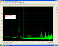
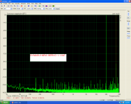
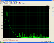
Servo experiments.
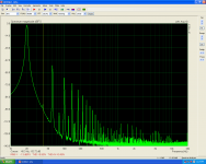
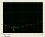
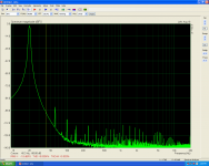
Yes my last modified circuit hasn't good performance in low frequencies
The distortion is high in low band.
See pictures 1&2.
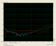
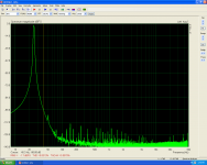
The first try after this was to increase the C12 value to 1uf.
See picture 3&4 better results but i have -4mv offset and very long settling time.
The second try was to change R28 VALUE from 6k8 to 22k.
Settling time is now 12'' and offset is zero.
See pictures 5&6
Yes my last modified circuit hasn't good performance in low frequencies
The distortion is high in low band.
See pictures 1&2.
The first try after this was to increase the C12 value to 1uf.
See picture 3&4 better results but i have -4mv offset and very long settling time.
The second try was to change R28 VALUE from 6k8 to 22k.
Settling time is now 12'' and offset is zero.
See pictures 5&6
Attachments
-
 0.47 1.1.PNG106.3 KB · Views: 357
 -
 steps 1.1.6k8 signal gnd.PNG69.8 KB · Views: 331
 -
 1.1.1.22k signal gnd ref steps.PNG68 KB · Views: 329
 -
 1.1.22k signal gnd.PNG106.9 KB · Views: 341
 -
 100W.PNG103.4 KB · Views: 155
 -
 1.1.1.22k.no 68k sign gnd 27.3 v a.c 7R.PNG104 KB · Views: 144
 -
 1.1.1.22k.no68k ref sign gnd steps.PNG70 KB · Views: 146
 -
 1.1.1.22k no 68k 25Hz.PNG103.8 KB · Views: 140
 -
 1.1.1.22k no 68k sig.gnd.PNG106.6 KB · Views: 328
Last edited:
Too late for edit.
Here is the circuit as tested in the last 5,5,7,8,9
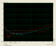
A final test using RMAA.
Here is the circuit as tested in the last 5,5,7,8,9
A final test using RMAA.
Attachments
-
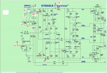 symasui-servo as tested.JPG150.4 KB · Views: 229
 -
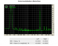 intrmodulation distortion.PNG22.6 KB · Views: 137
 -
 IMD swept tones.PNG17.7 KB · Views: 131
 -
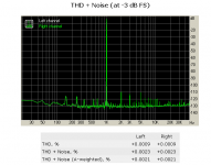 THD+noise.PNG22.8 KB · Views: 134
 -
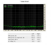 noise level.PNG22 KB · Views: 121
 -
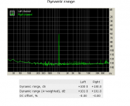 dynamic range.PNG21.2 KB · Views: 130
 -
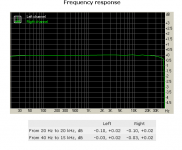 frequency response.PNG17.5 KB · Views: 209
 -
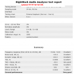 last.PNG20 KB · Views: 160
Last edited:
Well. You have received from the circuitry of everything it's capable of. You can solder the amplifiers with the best circuitry after some time.
Last edited:

Hi!
Above I explained why Japanese people made it so. You want to repeat it. But if you don't understand the reasons for the decision of the Japanese, you will have to rely more on God, than on circuitry. 🙂
I don't think your explanation is correct.
Q203 is a DC servo, taking its reference from the speaker terminals (which is a good idea by itself) - time constant of the integrator is 1 sec. Nothing to do with speaker cable resistance compensation. It makes no sence to compensate it in DC. AC is a different story, but it's not addressed in this circuit.
I do not offer my explanation as the only correct and detailed. But we don't have another point of view. 🙂I don't think your explanation is correct.
You can't link the choice of the connection point and the servo settling time. Doing so is wrong because the wires do not contain timing circuits, whose delay time can be compared with the 1 s.Q203 is a DC servo, taking its reference from the speaker terminals (which is a good idea by itself) - time constant of the integrator is 1 sec. Nothing to do with speaker cable resistance compensation. It makes no sence to compensate it in DC. AC is a different story, but it's not addressed in this circuit.
Your second assumption (regarding the fact that the servo works only on DC) is also incorrect. Look closely (for Onkyo 504): Opamp Q203 (the right half) is covered by 100% NFB loop via C215-С217. This opamp included a voltage follower for the current signal of the acoustic systems in the frequency range up to megahertz. The other half of the amplifier has a gain of -1: R235 / R233 in the frequency range up to megahertz. Our current view is different: you see servo a DC amplifier, I see the AC amplifier.
In the third place. Very bad decision - to take the referent to the servo near the back wall of the amplifier, a mile away from the clean signal GND. Such a connection forms a magnetic loop antenna. This loop adopts magnetic interference as we have seen in the graphs from thimios. Opamp amplifies the potential difference between the GND and the connection point of the servo. Therefore, we need to draw the Board as to protect this loop against interference with normal operation of the compensator the nonlinearity of the current speakers. Otherwise, we should take as referent the servo as close as possible to the clean signal GND to avoid interference.
You have to understand my thoughts, how would you not find it difficult to do so. 🙂
Last edited:
Try to change only C12. I think that C13 does not so much affect the distortion. Sufficient capacity C13 470 nF.First picture C12=1.5uf C13=1uf.
Second C12=1.5uf C13=1.8uf
- Home
- Amplifiers
- Solid State
- Revisiting some "old" ideas from 1970's - IPS, OPS