It may be caused by the difference in input LTP's base currents due to significant difference in base-to-ground resistors' values.
It would not be a problem if the input devices would be the jFETs or the tube triodes, but is a problem with BJTs.
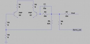
For a test, we can insert an electrolytic capacitor in series with NFB resistor, placed between the -IN and the signal ground.
For a test, we can insert an electrolytic capacitor in series with NFB resistor, placed between the -IN and the signal ground
Please show this on the schematic.
Last edited:
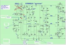
Ok please look on the schematic.
Is this what you say?
Adding the 220uf non polar. when R28 Is on the gnd offset is 140mV.(Without 220uf offset is 4v)
Is this what you say?
Adding the 220uf non polar. when R28 Is on the gnd offset is 140mV.(Without 220uf offset is 4v)
Attachments
Last edited:
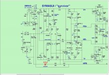
Ok please look on the schematic.
Is this what you say?
Exactly! Just also made a picture 🙂
Attachments
Just a moment...what is your recommendation?Exactly! Just also made a picture 🙂
A servo plus an electrolytic in feedback resistor?
Last edited:
But the base current is of the order of 6uA. That was confirmed some while ago and confirmed that the LTP was reasonably in balance (just within that tolerance of ±10%).
6uA across 22k is only 132mV.
changing one side to 11k only creates a difference of 66mV. That very approximately should become the new output offset.
The thing is even more strange - there's also R25 = 820R, between the -IN and the ground (bottom part of NFB divider). So our R28 = 22K is getting grounded in parallel with it - overall value change is negligible. Maybe it's not 22K?
Also, just to clarify with regards to offset values. Voltage gain with the feedback in place is close to 28. So, if we change the differential voltage between the inputs for, say, 100mV, the offset at the output will change for 100mV * 28 = 2.8V
Just a moment...what is your recommendation?
A servo plus an electrolytic in feedback resistor?
Let's first see what it shows with the electrolytic, but no servo:
- with R28 grounded;
- with R28 open.
And then with servo - r28 is just connected to the opamp output.
WITH the electrolytic,BUT NO SERVO and open R28 offset is 2.6mVLet's first see what it shows with the electrolytic, but no servo:
- with R28 grounded;
- with R28 open.
And then with servo - r28 is just connected to the opamp output.
WITH the electrolytic,BUT NO SERVO and R28 grounded offset=140mV
And then with servo - r28 is just connected to the opamp output.
Do you mean servo+electrolytic?
Last edited:
Also - what is the voltage between the power ground and the signal ground (if any)?
Negative lead is on the power ground.
Negative lead is on the power ground.
Valery to my point of view there isn't any reason for more modificationsYes.
The last schematic i have tried togethere with opa change from tl072 to lf412 is ok.
5'' from start up to 2.8mV is ok?
Last edited:
Valery to my point of view there isn't any reason for more modifications
The last schematic i have tried togethere with opa change from tl072 to lf412 is ok.
5'' from start up to zero is ok.
OK - no problem, but what is the voltage between the power ground and the signal ground? 🙂
Look at post #1662 ,this is 6mv(the 160mv measurement is against the power gnd),is this what you ask about?Also - what is the voltage between the power ground and the signal ground (if any)?
Negative lead is on the power ground.
Last edited:
Look at post #1662 ,this is 6mv,is this what you ask about?
Ah, ok, 160-154, I see.
What will be the next step?🙂Ah, ok, 160-154, I see.
The question is Servo or not Servo😕
To be or not to be😉
Last edited:
What will be the next step?🙂
The question is Servo or not Servo😕
To be or not to be😉
I think - leave it with LF412.
With LF412 or without servo😕I think - leave it with LF412.
Testing the no servo version i see better performances.
What will be the advantage using the servo?
Last edited:
With LF412 or without servo😕
Testing the no servo version i see better performances.
What will be the advantage using the servo?
There are 2 main reasons for using a servo:
1) Long term operation stability - over the time offset at the output may slip, but servo will correct it all the time, so no problem.
2) You can remove electrolytic capacitor from the bottom leg of NFB divider - offset with no capacitor is higher, but servo will correct it.
It's possible to solve both issues with no servo (with manual adjustment), but the input stage has to be very thermally stable (very low offset change as operating temperature changes).
Today i have test the Kypton v IPS whose servo is the same with Symasui.
What i found?
Kypton v start normaly with an offset about 400mv and fast go to 0v.
Symasui with servo never touch the 0v,always start from 3v and ended at 2.9mV.(same offset as in the non servo version).
Kypton v servo gnd is at the signal gnd,when Symasui servo gnd is at the power gnd.
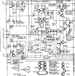
Here is a commercial solution.
What i found?
Kypton v start normaly with an offset about 400mv and fast go to 0v.
Symasui with servo never touch the 0v,always start from 3v and ended at 2.9mV.(same offset as in the non servo version).
Kypton v servo gnd is at the signal gnd,when Symasui servo gnd is at the power gnd.
Here is a commercial solution.
Attachments
Last edited:
- Home
- Amplifiers
- Solid State
- Revisiting some "old" ideas from 1970's - IPS, OPS