Note that the cheeks don't have to be at the extreme ends of the ferrite rod - move them inwards to form a more compact coil than the one you did earlier.
Regarding varnish: QTA Systems, to whom I linked earlier, say to use "coil locking lacquer", but since this is expensive, yacht varnish can be used instead - although it takes longer to dry.
P.S. Searching for "coil locking lacquer" takes me to the ebay transformer varnish we mentioned earlier!
Regarding varnish: QTA Systems, to whom I linked earlier, say to use "coil locking lacquer", but since this is expensive, yacht varnish can be used instead - although it takes longer to dry.
P.S. Searching for "coil locking lacquer" takes me to the ebay transformer varnish we mentioned earlier!
That’s actually quite interesting because I was just talking to someone about yacht varnish, and they said it’s basically polyurethane!
I will see what I can come up with for the ends of the ferrite rods next week when I resume.
I will see what I can come up with for the ends of the ferrite rods next week when I resume.
I got a PM back from the coil winding expert, who shall remain nameless. He told me he advised you to use a former here, but is doing other things right now. 🙄
Thing about doable audio projects is try to keep it simple. Try to reduce the area of innovation as much as you can. Otherwise you run into "The Law of Unexpected Consequences!".. 😱
Totally innovative designs run into all sorts of teething troubles. I prefer to limit my radical ideas to the largely tried and tested. After all, we are just replacing a midrange initially and improving a crossover. Not opening a coil winding shop.
I have no idea if polyurethane varnish might attack the commonly used plastic enamel on coil wire. So buy ready made. 😱
As I have said, there is no need to use varnish if you fix wooden cheeks on your ferrite rod.
Drill small holes through the cheeks through which to pass and secure the wire at the beginning and end of the wind.
Once the coil is soldered in place, the windings will be secure.
I wish I had never mentioned varnish in the first place! 😱
Drill small holes through the cheeks through which to pass and secure the wire at the beginning and end of the wind.
Once the coil is soldered in place, the windings will be secure.
I wish I had never mentioned varnish in the first place! 😱
He told me he advised you to use a former here
Yes he did. I wasn’t trying to go against advice and avoid using a former, but the suggested former was 23mm dowel. I went to Wickes (which is the only store near me) but they didn’t have any in stock, I also don’t own something like a pillar drill to get a perfectly centred hole through the middle… so I wound directly on the rod. The coil expert you’re talking about is also the one who advised me to use electrical tape around the outside, so I was quite confused when you said this wasn’t a good idea. 🙁 to my mind, I wasn’t doing anything dangerous and was quite pleased with the attempt but it’s very difficult to know what to do when one engineer says to wrap it with tape, and another says it might burn the house down :-/ anyway, it’s no problem, I’ll rebuild them without using tape. I’m also planning to initially run the speakers with the crossovers externally (as suggested by the coil expert) so I can monitor the temperature of the inductors after a long listening session. After all, the inductors will be covered by a large amount of foam in the cabinet so checking the temperature before assembling seems sensible. I have an IR thermometer to help with this.
As I have said, there is no need to use varnish if you fix wooden cheeks on your ferrite rod.
Drill small holes through the cheeks through which to pass and secure the wire at the beginning and end of the wind.
Once the coil is soldered in place, the windings will be secure.
This is what I plan to do.
I wish I had never mentioned varnish in the first place! 😱
I’m glad you did, I’ve learnt a lot about various varnishes 😉
I’ve just finished the 2nd 0.18mH air coil.
The resistance for this is about 0.28R using 1.25mm wire.
I do not think I will be able to achieve anywhere near 0.27R for the 0.82mH air coil BUT: I still have some ferrite rods… is it suitable to use ferrites here in the circuit? What are the pros/cons?
The resistance for this is about 0.28R using 1.25mm wire.
I do not think I will be able to achieve anywhere near 0.27R for the 0.82mH air coil BUT: I still have some ferrite rods… is it suitable to use ferrites here in the circuit? What are the pros/cons?
Don't worry about it.
I just make this stuff up as I go along. On a Monday I might do 0.3R, on a Tuesday I might do 0.5R... 😀
You are not going to hear it.
I just make this stuff up as I go along. On a Monday I might do 0.3R, on a Tuesday I might do 0.5R... 😀
You are not going to hear it.
Crossover is built.
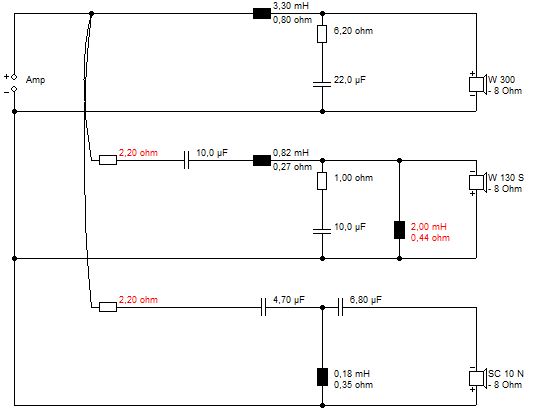
The 2.2R resistors at the start of the tweeter and mid circuits: do they control/affect volume by any chance? I briefly connected a tweeter and noticed that it was extremely quiet.
Is it correct to assume this can be reduced? Maybe a 1R?
The 2.2R resistors at the start of the tweeter and mid circuits: do they control/affect volume by any chance? I briefly connected a tweeter and noticed that it was extremely quiet.
Is it correct to assume this can be reduced? Maybe a 1R?
Yes, it's for level control.
You could start by shorting the 2.2 out to see the effect on the level without it in circuit.
You could start by shorting the 2.2 out to see the effect on the level without it in circuit.
I tested today at a moderate volume and checked the crossover temperature after an hour which is all the time I had. I measured 18C… across everything, so bass ferrite all the way up to the smaller aircoils. Resistors too. So just room temperature, I guess, no noticeable heat.
Tomorrow I’m gong to crank it up for a bit to see if they actually warm up some.
Do clarity caps have a run in period? I fancy there is slight lack of depth in places. The bass seems a bit weaker than before.
A win for the tweeters and mids though, clarity is good. I fancy I might need to reduce the mid resistance, but tweets are good.
Last edited:
I don't subscribe to the idea that film capacitors have "a run in period".
And, I'm not surprised that your inductors don't get hot under normal useage! 😉
Weak bass? It may just appear that way because the clarity of the mid and treble has improved.
What attenuating resistance did you end up using on your mid and tweeter?
What is the dc resistance of your bass coil?
And, I'm not surprised that your inductors don't get hot under normal useage! 😉
Weak bass? It may just appear that way because the clarity of the mid and treble has improved.
What attenuating resistance did you end up using on your mid and tweeter?
What is the dc resistance of your bass coil?
The DC resistance of the bass coils are 6.52 and 6.47.
At the moment the attenuating resistor for the tweeter I checked is back to 2.2R as in the crossover diagram. I bypassed the resistor on the tweeter briefly but having tried with and without it actually sounds better with. It seemed quiet initially but when both cabinets were finished and everything was in position they seemed better. The mids I haven’t changed, still 2.2R.
I’ll dig out some bassy tracks tomorrow and test, but today I found I wanted to dial up the bass to max to get it sounding balanced.
Sorry I’ve misread that as: what is the resistance of the bass drivers. Long day 😱
The resistance of the ferrite coils, the 3.3mH ones, is 0.4R. I used 1mm wire to keep it low.
The resistance of the ferrite coils, the 3.3mH ones, is 0.4R. I used 1mm wire to keep it low.
Last edited:
😀 my fault really, I read coil and for some reason had voice coil = driver in my head. Maybe I should hit the hay and continue tomorrow after a large coffee.
Listening to a range of things today. We’ve repositioned them, and the bass seems a little better. Is it worth fitting a port? I noticed these cabinets don’t have one.
Tweeters are good but I feel the mids are a bit dull/muffled. Would the attenuating resistor be responsible for this or is that just the volume of the mid circuit?
Tweeters are good but I feel the mids are a bit dull/muffled. Would the attenuating resistor be responsible for this or is that just the volume of the mid circuit?
You can't just go about "fitting a port" for reasons I am not going to go into.
Suffice it to say, yours is a sealed box design.
Have you tried bypassing the attenuating resistor on the mid to answer your own question?
Perhaps you should have settled for simply replacing the capacitors in your original crossover, as I recommended in post #6!
Do I sound frustrated? 😀
Also, its a good idea to modify only speaker of the pair at a time. That way you can compare the audible effect of crossover component/configuration changes.
Last edited:
- Home
- Loudspeakers
- Multi-Way
- Restoring / Modifying Goodmans Magnum K2s Advice Needed