Fwiw, I did replace the caps in the original crossover. I bought Mundorf NPEs as you recommended and it made little difference, hence embarking on this journey.
Since the cabinets are assembled and it’s not a short task to remove the bass driver then crossover and change/remove the resistor, I thought I’d ask in case the answer was just volume.
But anyway, thanks everyone for all your help. I think we’ve come to the end of this journey 🙂
Since the cabinets are assembled and it’s not a short task to remove the bass driver then crossover and change/remove the resistor, I thought I’d ask in case the answer was just volume.
But anyway, thanks everyone for all your help. I think we’ve come to the end of this journey 🙂
OK, but that response begs a final question.
Do the speakers now sound better or worse than when they were in their untouched, original form?
And, regarding the mid's resistor, it will only affect level, it should not 'muffle' the sound picture.
Do the speakers now sound better or worse than when they were in their untouched, original form?
And, regarding the mid's resistor, it will only affect level, it should not 'muffle' the sound picture.
Better in some ways, worse in others.
What I mean by that is:
Tweeters - definitely more detail than the goodmans, they’re ok with the 2.2R but too loud without. Somewhere in between is probably the answer.
Mids - definitely louder than the original goodmans and there’s more detail than the goodmans but if you compare the midrange to the likes of the 2 way tannoys I just collected, there’s definitely more clarity in the tannoys. This really surprised me since the tannoy is only 2 way.
Bass - Maybe it’s like you say, now the mids and tweeters are improve, the bass is less noticeable. Before changing the mid/tweet/crossover I didn’t feel the need to turn the bass dial to max, now I’d say it’s a must.
So overall they’re different. I wasn’t expecting ££££s of speaker performance out of £200 investment, but I was hoping they would beat other £200 speakers. Comparing them to some Roth Oli40s that I paid £205 for new, the Roth’s win hands down on depth of bass and details in the mids. I find myself wondering how the alternative option planet10 suggested would have sounded. Maybe I should have done one of each. Maybe it’s the Faital midrange that’s the problem, maybe it’s my coils. They’ve been redone though, although I did have to use a ferrite for the 0.82mH, not an aircoil. I have no idea if this had any bearing.
In terms of money spent (as I am sure you’ll want to know) the most expensive parts were the caps/drivers (£165). Most of the other stuff (like varnish, grille fabric, foam) has been picked up from freecycle/neighbours/friends etc or I already had in the shed from years of stripping stuff and / or hoarding crap (wire, spikes, foam tape for gaskets, black spray paint, Velcro, liquid nails, MDF etc). I’m sure if I wanted to recoup or transplant some of that investment most of it could be recovered. The only un-reusable part is the custom grille badge and obviously the varnish/dye/glue which can’t be reused.
I’ve learnt a lot doing this, and that’s the best part of all. I’m always up for learning something new, even if the outcome wasn’t quite as I expected. Or I have to redo something because it’s not safe. If anything else, it’s been fun.
It troubles me that you now have to turn the bass control up to maximum.
I can't help but think this may be due to a mistake in the crossover wiring, an inappropriate component value or a driver phasing issue.
As you say, regardless of the outcome, the fun is in the learning process.
I can't help but think this may be due to a mistake in the crossover wiring, an inappropriate component value or a driver phasing issue.
As you say, regardless of the outcome, the fun is in the learning process.
My first thought was that I’d made a mistake in the crossover.
I checked the component values: caps and inductors (using LCR meter), resistors too. I also checked for errors in the circuit. I rechecked, then the Mrs checked too. We’re both confident the crossover is as the diagram is. 2mm wire was used between the crossover boards and drivers (overkill I know but it was in the shed), soldering is shiny, flux was used, no dry or dull joints. Not the absolute tidiest arrangement but I’m confident nothing is loose, shorting etc. We also looked at the position of inductors and other components to each other: inductors are spread out and at right angles.
Here, have a look:

We did end up using hot glue in the end. I think it looks messy but it’s melting point is ~200C. No electrical tape at all.
I checked the component values: caps and inductors (using LCR meter), resistors too. I also checked for errors in the circuit. I rechecked, then the Mrs checked too. We’re both confident the crossover is as the diagram is. 2mm wire was used between the crossover boards and drivers (overkill I know but it was in the shed), soldering is shiny, flux was used, no dry or dull joints. Not the absolute tidiest arrangement but I’m confident nothing is loose, shorting etc. We also looked at the position of inductors and other components to each other: inductors are spread out and at right angles.
Here, have a look:
We did end up using hot glue in the end. I think it looks messy but it’s melting point is ~200C. No electrical tape at all.
Very nice work, David! No expense spared! 😀
I shall run the sim again to see what is going on with the bass.
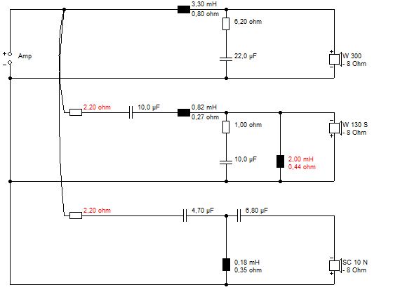
This was the filter before I added the 2mH.

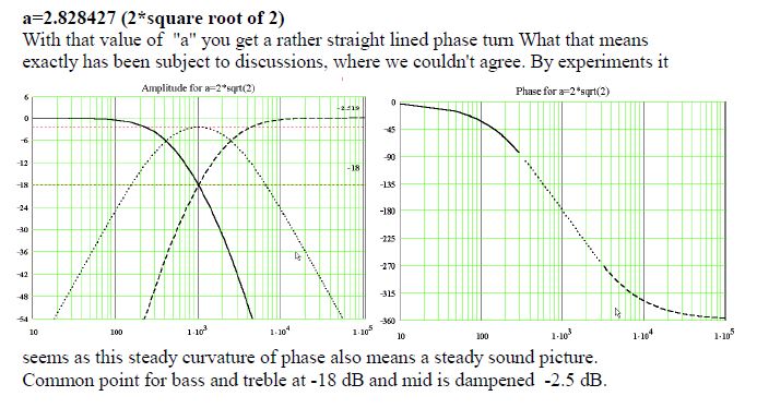
Where we are trying to get is this:
I would hope you just adjust two red 2.2R resistors. They were complete guesswork.
I shall run the sim again to see what is going on with the bass.
This was the filter before I added the 2mH.
Where we are trying to get is this:
I would hope you just adjust two red 2.2R resistors. They were complete guesswork.
The usual reason for a lack of bass and a vague midrange is that the bass drivers are wired out of phase with each other.
It couldn't be as simple as that, could it?
Your work on the actual crossover boards is very neat and no doubt accurate, but you may just have the wires to one of the woofers the wrong way round.
It's worth checking!
It couldn't be as simple as that, could it?
Your work on the actual crossover boards is very neat and no doubt accurate, but you may just have the wires to one of the woofers the wrong way round.
It's worth checking!
Last edited:
There is a simple test for correct bass polarity...
Face the two speakers to each other about 1cm apart. Listen to the bass. If they are wired out of phase, the bass will almost disappear or cancel out. Swap one of the speakers on polarity, and the bass will then reappear. Magic!
I have done this on some old Celestion Ditton 44 speakers which were wired out of phase by the previous owner. No wonder he sold them! 😀
Very nice work, David! No expense spared! 😀
Your work on the actual crossover boards is very neat
Thank you both. 😎
Now about the possible incorrect polarity of the bass drivers, I tested at first as you suggested Steve and it didn’t seem to cancel out. Sat side on to them with them so close though, it seemed a bit better but obviously cannot leave them like that!
So I removed both bass drivers and this is what I see:


Both drivers are the same, the red dot on the same side indicating positive. I double checked while I was there and the drivers positive red wire goes to the correct point on the board.
Unless it’s possible that they are labelled incorrectly? The factory red wire was definitely that side. The red dot couldn’t be the wrong side on both? I don’t know anyone else with a pair of these to check. Surely that doesn’t happen?
I can’t edit the previous post any more so I’ll just add that the above pics are the same driver, it only occurred to me take a photo on the second one. But they both look the same.
To be sure, perform the battery check.
Both bass driver cones should move in the same direction when connected in the same way to the battery.
Both bass driver cones should move in the same direction when connected in the same way to the battery.
The standard is that, when the terminal with the red dot is connected to battery positive, the cone moves outwards, away from the magnet.
It seems unlikely that one of the drivers has its voice coil reverse connected at its terminals compared to the other.
It seems unlikely that one of the drivers has its voice coil reverse connected at its terminals compared to the other.
I'm just going to contribute to your knowledge base here. 😎The red dot couldn’t be the wrong side on both?
Only if the red dot had been incorrectly stuck on the opposite terminal of one of the drivers compared to the other would there be a chance of reverse phase connection
Looking at your top photo of your woofer, I can trace its 'internal' wiring from the woofer terminals all the way back the voice coil at the centre. There should be no problem if the 'internal' wiring of the other woofer looks the same.
Ok, I will double check later this evening when I get back. A 9V battery you say? Like a smoke alarm battery?
Yes, but it's just a double check since your speakers appear to have passed Steve's bass cancelling test.
Done. Both drivers move outwards when the red wire was connected to positive. A very clear outward movement.
I’ve been trying to think of other things I could have done wrong… (I know the answer to these things is probably no, I’m clutching at straws here)
1. Could it be that I haven’t put enough BAF in the mid enclosure? I put a wad but it’s not tight tight.
2. The gasket material I used for the bass driver is a foam tape that is dense and approx 4mm thick, should it be a bit thinner? (Ie so more of the metal surround of the driver is ‘in contact’ with the baffle (I’m really scraping the barrel here)). The drivers are nicely screwed to the baffle, pulled down and nice and tight though.
Sorry, I don't see any problems with either suggestion.
The BAF wadding should not be compressed and the gasket is successfully sealing your driver surround against air leaks.
The BAF wadding should not be compressed and the gasket is successfully sealing your driver surround against air leaks.
Your hopes may now lie with Steve's review of his crossover circuit.
The only other suggestion I can think of to make the bass subjectively louder is by further attenuating the mid and tweeter, but that's me clutching at straws!
The only other suggestion I can think of to make the bass subjectively louder is by further attenuating the mid and tweeter, but that's me clutching at straws!
I thought not but wanted to check. I guess the next step is see if anything turns up when Steve sims it again.
On a different note, I learnt just now that you can run inductors in parallel and series and they behave the same way as resistors. For example, I estimated that the 0.82mH air coil would be about 0.6R with the 1.25mm wire I have so I ended up using a ferrite. It is in fact also an option to make the 0.82mH air coil twice, and run them in parallel to half the resistance. Something useful for another time. 🙂
Edit: oops, was still typing and didn’t notice you’d posted the above.
- Home
- Loudspeakers
- Multi-Way
- Restoring / Modifying Goodmans Magnum K2s Advice Needed