@Galu, thanks for taking the time to explain that. There is plenty here I don’t understand but I have enjoyed the journey so far. 🙂
@system7 just looking at viability here for units that require that 5L.. how air tight does that 5L VAS have to be? One thing could be to simply create a partition and use liquid nails and silicone to ensure it’s as air tight as possible. There was a SIGNIFICANT amount of foam in there, 2 pieces in each cabinet measuring approx 43cmx34cmx8cm, presumably for reflections from the bass driver as the mids and tweeters were sealed? Obviously not all of this would be able to go back in there, maybe just the one behind the woofer is sufficient? This would allow for a larger hole to be cut and satisfy the 5L VAS requirement for some of the louder mids? Got plenty of MDF in the shed, these cabinets are already pretty heavy. I doubt a bit more composite wood would notice a difference. Obviously would have to take some measurements and calculate but seems doable with little effort.
@system7 just looking at viability here for units that require that 5L.. how air tight does that 5L VAS have to be? One thing could be to simply create a partition and use liquid nails and silicone to ensure it’s as air tight as possible. There was a SIGNIFICANT amount of foam in there, 2 pieces in each cabinet measuring approx 43cmx34cmx8cm, presumably for reflections from the bass driver as the mids and tweeters were sealed? Obviously not all of this would be able to go back in there, maybe just the one behind the woofer is sufficient? This would allow for a larger hole to be cut and satisfy the 5L VAS requirement for some of the louder mids? Got plenty of MDF in the shed, these cabinets are already pretty heavy. I doubt a bit more composite wood would notice a difference. Obviously would have to take some measurements and calculate but seems doable with little effort.
I noticed there were 3 capacitors and three coils and no resistors. Rearrange those 6 into a well known crossover. 😀=
Probably lookslike this:
dave
Attachments
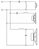
Just sat down and followed the wires. It’s almost like the above, but the woofer’s coil is on the negative. Excuse the crappy drawing.

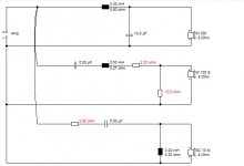
I ran Dave's ideas up the flagpole with a 4" midbass in 2L and otherwise similar drivers.
Not a million miles away from a SEAS 503:
SEAS Kit 503
But here the mid is more of a narrowband filler driver.
I was guessing where the 2X 5uF and 10uF go. I couldn't get the optimiser in Boxsim to work with the Visaton fullrangers due to incomplete files, and didn't want to spend time doing it manually. But no reason to think they wouldn't work, though some issue with high Qts, being designed for open baffle or enclosure-less ceiling mounting. Need biggish enclosures in other words.
To make chipboard enclosures requires some accuracy cutting for airtightness on the sidepieces. I bought a sheet from B&Q and they machined 8 squares around 20cm and 2 bigger backs to fit. Around 7L. You get a certain number of cuts for free from B&Q.
Attachments

I ran Dave's ideas up the flagpole with a 4" midbass in 2L and otherwise similar drivers.
Not a million miles away from a SEAS 503:
SEAS Kit 503
But here the mid is more of a narrowband filler driver.
I was guessing where the 2X 5uF and 10uF go. I couldn't get the optimiser in Boxsim to work with the Visaton fullrangers due to incomplete files, and didn't want to spend time doing it manually. But no reason to think they wouldn't work, though some issue with high Qts, being designed for open baffle or enclosure-less ceiling mounting. Need biggish enclosures in other words.
To make chipboard enclosures requires some accuracy cutting for airtightness on the sidepieces. I bought a sheet from B&Q and they machined 8 squares around 20cm and 2 bigger backs to fit. Around 7L. You get a certain number of cuts for free from B&Q.
Well, assuming that the enclosure size quoted on these drivers is a minimum requirement, I can get about 9.6L of sealed space the for the midrange and just cut the hole to fit.
I’ve just used cardboard to see what kind of sizes we get and 2 cuts of MDF measuring about 20cm x 20cm x 24cm = 9600cm3 = 9.6L
Before:

After:

View from mid cut out:

I could easily do this with chipboard or MDF from the shed. Liquid nails / PVA / Silicone to seal and fix in place. Would have to drill a hole somewhere to pass wire through obviously then seal it up, but not a problem. The foam was placed into the cabinet in 2 right angles. So if you lay the cabinet on it’s back, the side view is this this:

Obviously the piece below the tweet and mid would have to be removed. Not sure how that would affect the sound from the bass driver, am hoping it should still be ok. Can cut some and place in the area behind tweeter and into the new mid enclosure though.
Does this open the way for more suitable drivers?
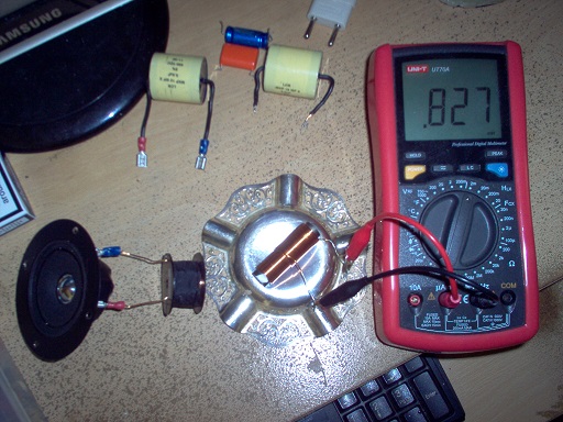
This is a tricky problem based on incomplete knowledge. I would certainly draw up the schematic of the crossover complete with exact values and polarities. But I have a goodish multimeter that can measure coils and capacitors and the DC resistance of drivers:
We seem to have whittled the afforadable mids down to two, The Faital Pro 4FE32 and 5FE120:
FaitalPRO | LF Loudspeakers | 4FE32 (8Ω)
I think you could make a thick cardboard gasket to get that one to seal on a 10cm cutout.
FaitalPRO | LF Loudspeakers | 5FE120 (8Ω)
That one needs the cutout filed bigger. Doesn't take long with a rounded wood file.
Based on the Vas and the Qts, a simple calculation for closed box says 5L will be good for either. If you are interested, this is the formula:
Volume of cabinet = Vas / ((Qtc / Qts)^2 - 1) where Qtc is the desired Q of the box, usually 0.7. Thus the 5" is Qts = 0.5, so we get (0.49 / 0.25) - 1 = 1 and the box is 5L like the Vas. A little smaller will do no harm with a mid because you are not interested in the bottom end, with a bass it will constrain the bass response.
Having loudness to spare on a mid allows you to use an attenuator, which helps with response and impedance.I don't really know what state the tweeters are in, but have seen enough that I would take this on. A bit of crossover adjustment might be in order, but nothing difficult or expensive.
Last edited:
That’s great Steve, thanks.
I have an Aneng AN8008 meter here which should be able to take accurate measurements. I can take measurements of the bass drivers and the crossover components? I assumed that this would be taken with the meter on the Ohms setting, but it looks like your meter is set to something else (can’t make out what it is). This meter is auto range:

Just set to Ohms and run across the driver terminals?
I am going to place an order for the Faital 5FE120’s and make the hole larger, then construct something internally. I think this would be the best option.
I don’t have a problem knocking together new crossover circuits, I can solder and follow circuits, I just don’t know what needs to go where and will default to your best judgement.
Poly caps and other components are so cheap on AliExpress, I can get whatever is needed for entirely different crossovers if that’s the way to go.
I have an Aneng AN8008 meter here which should be able to take accurate measurements. I can take measurements of the bass drivers and the crossover components? I assumed that this would be taken with the meter on the Ohms setting, but it looks like your meter is set to something else (can’t make out what it is). This meter is auto range:
Just set to Ohms and run across the driver terminals?
I am going to place an order for the Faital 5FE120’s and make the hole larger, then construct something internally. I think this would be the best option.
I don’t have a problem knocking together new crossover circuits, I can solder and follow circuits, I just don’t know what needs to go where and will default to your best judgement.
Poly caps and other components are so cheap on AliExpress, I can get whatever is needed for entirely different crossovers if that’s the way to go.
That looks like a standard meter. Good for DC resistance. You should touch the test leads probes together for calibration, because they have a finite resistance. Then subtract that voltage from what you get with the test resistance for accuracy.
Seems to have a signal generator, which might have uses with a second simple meter. You'd wire a known (say) 1mH coil in series with the test coil and insert a test tone around 1kHz. The AC voltages should then divide as the ratio of the coils.
My meter (£70 at the time, cheaper now) has a H (Henry) and F (Farad) scale. It uses a 1kHz test tone to estimate inductance H, but I always calibrate it with a known inductance because it is erratic on different scales.
I usually suggest people measure cutouts and rebates to see what will fit. Photos help too.
If you haven't read it yet, Troels' renovation is about what you might end up with:
SEAS Kit 503
Goodish sort of speaker. I used to have the similar Ditton 44 which was awesome, but had too many faults to correct in the end. One of the basses had fraying tinsel leads. But could it go loud! 😀
That looks like a standard meter. Good for DC resistance. You should touch the test leads probes together for calibration, because they have a finite resistance. Then subtract that voltage from what you get with the test resistance for accuracy.
Ok, here are the DC readings from the bass drivers to start:
Probes measured 0.08
1. 6.60 - 0.08 = 6.52
2. 6.55 - 0.08 = 6.47
My meter (£70 at the time, cheaper now) has a H (Henry) and F (Farad) scale. It uses a 1kHz test tone to estimate inductance H, but I always calibrate it with a known inductance because it is erratic on different scales.
If it would be advantageous to get such readings, I’m always up for extra tools…
I usually suggest people measure cutouts and rebates to see what will fit. Photos help too.
Here we go:


If you haven't read it yet, Troels' renovation is about what you might end up with:
SEAS Kit 503
Goodish sort of speaker. I used to have the similar Ditton 44 which was awesome, but had too many faults to correct in the end. One of the basses had fraying tinsel leads. But could it go loud! 😀
Yes I did read it, and I think if these K2s end up somewhere in this region I would be extremely happy. 😀
Faitals are here. Readings are:
1. 3.22 - 0.08 = 3.14
2. 3.23 - 0.08 = 3.15
Looks like I’ll only have to increase the mid cut out ever so slightly. They almost fit!
1. 3.22 - 0.08 = 3.14
2. 3.23 - 0.08 = 3.15
Looks like I’ll only have to increase the mid cut out ever so slightly. They almost fit!
Faitals are here. Readings are:
1. 3.22 - 0.08 = 3.14
2. 3.23 - 0.08 = 3.15
Looks like I’ll only have to increase the mid cut out ever so slightly. They almost fit!
FaitalPRO | LF Loudspeakers | 5FE120 (8Ω)
That was quick! But David, you've ordered the 4 ohm version: 😱
It's doable, especially as we should have level to spare, but limits our options a bit here.
It's always hard to keep impedance high in a three way.
Sounds like a plan. I think it's likely the 4 ohm could be made to work, but would need to sim it. I am off out this afternoon, but will have a look at the circuit for an 8 ohm this evening.
Ok, so maybe the simplest thing to do would be to decrease the cutout size.
Seems like lining the cutout with self stick closed cell foam tape would be the easiest.
Was that Blue Aran at Swaythling near Southampton who were so fast?
I think we have gone with the flattish 5" 8 ohm 89dB Faital Pro here, GM. It's a bigger 110mm cutout, so just a bit of filing needed.🙂
All happy days on the crossover. I think 4 ohms would have been awkward. It's a bit better than the Goodman's one IMO. About 5L for the mid as I suggested.
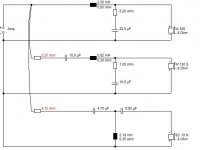
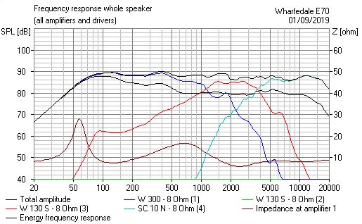
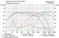
The drivers I used were a 91db Bass, a 86dB mid and a 90dB tweeter. But it's a very standard circuit with a bit of level adjust available with the red resistors.
The Visaton W130S has a peak at 1.4kHz that shouldn't be evident with the Faital. The tweeter crossover is Celestion's old standard 3.5kHz filter. Works well with most 6 ohm tweeters.
All that is needed is to adjust two resistors for loudness. If it is a 93dB woofer, 2.2R or 3.3 on the mid and 2.2R on the tweeter might be about right for a slight downward domestic slope.
I would use NP electrolytics in the bass and mid sections. Cheapish Metal Film on the tweeter. The 1R on the mid shunt could probably go with NPE types. Aircoils as much as possible, but ferrites often used on the bass. Resistor on the bass should be 10W ceramic type. Maybe even two 12 or 15R in parallel for 20W. The rest could be 5W types IMO. But 10W will do no harm on the mid.
I think we have gone with the flattish 5" 8 ohm 89dB Faital Pro here, GM. It's a bigger 110mm cutout, so just a bit of filing needed.🙂
All happy days on the crossover. I think 4 ohms would have been awkward. It's a bit better than the Goodman's one IMO. About 5L for the mid as I suggested.
The drivers I used were a 91db Bass, a 86dB mid and a 90dB tweeter. But it's a very standard circuit with a bit of level adjust available with the red resistors.
The Visaton W130S has a peak at 1.4kHz that shouldn't be evident with the Faital. The tweeter crossover is Celestion's old standard 3.5kHz filter. Works well with most 6 ohm tweeters.
All that is needed is to adjust two resistors for loudness. If it is a 93dB woofer, 2.2R or 3.3 on the mid and 2.2R on the tweeter might be about right for a slight downward domestic slope.
I would use NP electrolytics in the bass and mid sections. Cheapish Metal Film on the tweeter. The 1R on the mid shunt could probably go with NPE types. Aircoils as much as possible, but ferrites often used on the bass. Resistor on the bass should be 10W ceramic type. Maybe even two 12 or 15R in parallel for 20W. The rest could be 5W types IMO. But 10W will do no harm on the mid.
Attachments
Last edited:
That’s a great suggestion GM, thank you. I’ve ended up with the 5” Faital drivers for mids, but I’ve ordered some foam tape to replace the bass driver gaskets and should have some spare in case it’s needed.
@system7 got it. I’ll see what I can find and post back if I run into difficulty.
Edit: yes it was Blue Aran for the first order but not for the second. And yeah they were lightning quick 😀
Edit2: for the mid, exactly 5 or larger ok? Easier to do larger but can do 5 if needed.
@system7 got it. I’ll see what I can find and post back if I run into difficulty.
Edit: yes it was Blue Aran for the first order but not for the second. And yeah they were lightning quick 😀
Edit2: for the mid, exactly 5 or larger ok? Easier to do larger but can do 5 if needed.
Last edited:
I think 5L will work nicely. These things are not exact, especially as the mid crossover has no shunt inductance to take the bass down here. The box calculation breaks down with mid circuits. But looks good enough at 100Hz on the mid to me. A bit of stuffing with BAF is always good. That's the stuff like pillow filling.
I modelled it in 5L. Celestion used about 4L on a 5" mid.
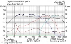
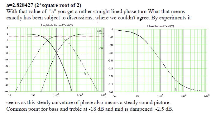
The actual theory says you aim at this for studio monitor flatness:
Box size can be a trade off, bigger loses power handling.
I modelled it in 5L. Celestion used about 4L on a 5" mid.
The actual theory says you aim at this for studio monitor flatness:
Box size can be a trade off, bigger loses power handling.
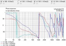
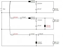
I tried to stick to the original Goodmans circuit, partly to keep it simple, but this afternoon had a look at a 2mH shunt coil on the mid circuit.
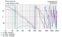
You can see this gets much closer to the Steen Duelund theory above. Even phase is better. It's a simple add on. The dotted lines are more the original circuit.
You can see that the mid bass response and enclosure size is now largely irrelevant. This is what I would call a proper job. Troels would do it like this... 😎
Attachments
Nice one Steve. Thank you so much for all your effort and help on this. It is truly appreciated! I’m pretty excited to see the end result 😀
I’m progressing with the parts list (albeit slowly) and will post once complete. I’m not working Thursday so will probably get it done then.
I’m progressing with the parts list (albeit slowly) and will post once complete. I’m not working Thursday so will probably get it done then.
- Home
- Loudspeakers
- Multi-Way
- Restoring / Modifying Goodmans Magnum K2s Advice Needed