Progress!
3 Changes. 1) Removed 10k resistor 2) Secured physical wires in J2 plastic connector and ensured secure connection to board from transformer to the best of my ability. 3) Soldered small wire per previous post and checked continuity with DMM and 9V to ensure relay engaged. Yes.
So, even though I may not need to do this, when I intentionally change something, I go back to square 1 with measurements.
Power on - sadly, into protection again, but wait... there's more.
No DC at L1 and L2.
Voltage across R417 - 295mV
Cathode (Stripe) side of D403: 44V5
Anode side of D403: 44V6
Pin 1 - Junction of U1 and R409, R412: (-)129mV - Seems much steadier.
Pin 2 - Junction of U1 and R407, R411 and positive side of C414: (-1.7mV)
Pin 3 - Junction of U1 and R414: 345mV
Pin 4 - Assume it's got solid continuity to GND
Pin 5 - Junction of U1 and R419: (-)0V745
Pin 6 - Junction of U1 and R423: 44V5
Pin 7 - Junction of U1 and R420: (-)0.08mV
Pin 8 - Junction of U1 and R413: 0V845 but rising.
Pin 9 - Junction of U1 and R413 (opposite side of R413 to Pin 8): 3V2
Short tests
Pin 1 - Very small delay, LEDs out, "CLICK!"
Pin 2 - No change
Pin 3 - No change
So... over-current.
It sounds like the relay circuit is working now. Next you need to figure out why the protection circuit is active.
@korpberget - It tested OK, and I cleaned all leads / tinned and soldered after pulling it out for a check. After I get to root cause, I'll replace it either way. I am not 100% sure, but I think this board has been out for repair before my buddy passed it to me and/or he may have purchased it used. I'll ping him later.
@jwilhelm. Yep. Seems I was potentially handed a "dual" issue. A real fault along with a dodgy protection circuit / PSU board.
So, here is the current status. The amp (while I was having breakfast), left protection. And guess what!? Music - directly from the speaker terminals...
So now, it's not the IF the amp will leave protection and engage the relay, it's WHEN.
Can anyone help re: what may control the timing?
Here is a new set of readings from the board - note the amp is not in protection:
No DC at L1 and L2.
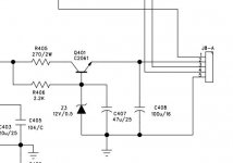
Voltage across R417 - 29V1 Hot leg to GND: 44V75 Other leg: 15V7
Cathode (Stripe) side of D403: 15V7
Anode side of D403: 44V6: 1V2
Pin 1 - Junction of U1 and R409, R412: (-)380mV - Seems much steadier.
Pin 2 - Junction of U1 and R407, R411 and positive side of C414: (-1.7mV)
Pin 3 - Junction of U1 and R414: 345mV
Pin 4 - Assume it's got solid continuity to GND
Pin 5 - Junction of U1 and R419: (-)0V72
Pin 6 - Junction of U1 and R423: 1V2
Pin 7 - Junction of U1 and R420: (-)0.08mV
Pin 8 - Junction of U1 and R413: 1V4 and steady
Pin 9 - Junction of U1 and R413 (opposite side of R413 to Pin 8): 3V2
@jwilhelm. Yep. Seems I was potentially handed a "dual" issue. A real fault along with a dodgy protection circuit / PSU board.
So, here is the current status. The amp (while I was having breakfast), left protection. And guess what!? Music - directly from the speaker terminals...
So now, it's not the IF the amp will leave protection and engage the relay, it's WHEN.
Can anyone help re: what may control the timing?
Here is a new set of readings from the board - note the amp is not in protection:
No DC at L1 and L2.
Voltage across R417 - 29V1 Hot leg to GND: 44V75 Other leg: 15V7
Cathode (Stripe) side of D403: 15V7
Anode side of D403: 44V6: 1V2
Pin 1 - Junction of U1 and R409, R412: (-)380mV - Seems much steadier.
Pin 2 - Junction of U1 and R407, R411 and positive side of C414: (-1.7mV)
Pin 3 - Junction of U1 and R414: 345mV
Pin 4 - Assume it's got solid continuity to GND
Pin 5 - Junction of U1 and R419: (-)0V72
Pin 6 - Junction of U1 and R423: 1V2
Pin 7 - Junction of U1 and R420: (-)0.08mV
Pin 8 - Junction of U1 and R413: 1V4 and steady
Pin 9 - Junction of U1 and R413 (opposite side of R413 to Pin 8): 3V2
I'm still trying to wrap my head around how the circuits operate but I think you are having issues in your voltage loss detection circuit. What pin were you shorting to make the relay operate?
Voltage readings with a meter are sometimes useless in these circuits as the meter can't display actual voltages fast enough to show what's happening. Voltage loss detection is usually a sine wave, the meter will give you a random reading in this sine wave. A scope is much easier to use here.
Voltage readings with a meter are sometimes useless in these circuits as the meter can't display actual voltages fast enough to show what's happening. Voltage loss detection is usually a sine wave, the meter will give you a random reading in this sine wave. A scope is much easier to use here.
Last edited:
@jwilhelm - Pin 1
It seems like the voltages at Pins 1 and Pin 8 change the most dramatically from the potential control side. I am digging in, re-reading Douglas' posts and looking at the schematic. I think I understand why Pin 6 changes after the relay engages.
It seems like the voltages at Pins 1 and Pin 8 change the most dramatically from the potential control side. I am digging in, re-reading Douglas' posts and looking at the schematic. I think I understand why Pin 6 changes after the relay engages.
Last edited:
FWIW - I powered down the amp, let it sit for a bit. I hooked up a speaker to get a more audible signal when the amp left protection.
At ~5 mins it left protection and went back into protection. It cycled in and out of protection for about 6 or 7 cycles over the course of a minute or so, then it finally left protection permanently.
Edited to add - Also a potentially valuable data point - If I power down the amp, and immediately power it back up, the protection goes off after a very short delay and stays off.... Spitballing - Caps draining and charging?
Edited again to add - I still don't have the blue "power" LED even after the relay engages. Could this possibly be related?
Last edited:
It is in the voltage loss circuit then. Its probably best to verify that R416, R412, R409 and R410 are reasonably close to their correct values but I would be suspecting C413 is in it's dying days and allowing too much ripple on pin 1.
It's hard to keep up with the edits!😀 The blue led is simply a power LED. It's fed from a basic regulator circuit through pin 2 of J8. You should have full rail voltage on one side of R405. You should have around 12V on the stripe side of Z3 and around 11.5V on pin 2 of J8.
Attachments
Last edited:
LOL! Apologies. It's particularly hard when reading the initial post from the e-mail.
So, good voltages there. It goes to show I still have a ton to learn from both examining the physical side of things and following schematics, but... There is still something funky with J2. I took out the LED board after checking the voltages, lo and behold... Blue LED flickers. Traced it back to my old friend J2. I'm going to disassemble the female completely, examine the innards and see if there's a bad crimp, clean the contacts inside, and put it back together.
Sheesh!
Thank you very, very much.
The amp is likely at the age where all the headers will be starting to tarnish. A good cleaning with Deoxit followed by some good contact lube usually helps a lot here. If you see any signs of heat do yourself a favor and just replace the header and connector. They will fail again shortly after cleaning.
It is in the voltage loss circuit then. Its probably best to verify that R416, R412, R409 and R410 are reasonably close to their correct values but I would be suspecting C413 is in it's dying days and allowing too much ripple on pin 1.
I dug and dug around. Still going to order new caps to replace, but I'd love to test this theory. I don't have any 1uF caps in my stash. Would going lower or higher in capacitance be acceptable as long as the voltage rating is 100V or higher? Closest I have on hand at the moment is 10uF 50V (may be borderline for permanent use on voltage rating) or 0.1uF film cap at 100V. I understand the fundamentals of caps for cross-overs and filtering / ripple reduction, but I can't determine proper values.
The amp is likely at the age where all the headers will be starting to tarnish. A good cleaning with Deoxit followed by some good contact lube usually helps a lot here. If you see any signs of heat do yourself a favor and just replace the header and connector. They will fail again shortly after cleaning.
No heat, but I cleaned the heck out of all the contacts. Still intermittent, but the only issue at the moment is the LEDs, so rather than make matters worse, I'll leave it be for the moment.
This is actually a filter so a 1uF cap is needed. 50V is likely lots here but if ordering I would go with 100V.
I do all this sort of housekeeping with a microcontroller in my amps, I prefer the digital domain for timing and detection but if I have the circuit figured out correctly pin 1 is a voltage loss detection circuit so when power is shut off it instantly mutes the output of the amp so you don't hear shut-down noises. Pin 8 is an on delay circuit so you don't have power up noises. Pin 2 is supposed to be a DC detection input but they have temp sensors hooked to it. Pin 3 is where they hooked DC detection circuits for both channels. I don't see over-current detection.
I do all this sort of housekeeping with a microcontroller in my amps, I prefer the digital domain for timing and detection but if I have the circuit figured out correctly pin 1 is a voltage loss detection circuit so when power is shut off it instantly mutes the output of the amp so you don't hear shut-down noises. Pin 8 is an on delay circuit so you don't have power up noises. Pin 2 is supposed to be a DC detection input but they have temp sensors hooked to it. Pin 3 is where they hooked DC detection circuits for both channels. I don't see over-current detection.
@jwilhelm -
Thank for you for the explanation. I just wasn't sure if filtering "above" or "below" a certain frequency by going higher or lower in capacitance would be okay for a temporary check.
Yes, I have 100V caps in my cart, but I was just going to give something a try in the interim.
Truly appreciate the clear, but simple explanation.
Well, work will pause until we get some parts.
To get the amp operating you need to shift the voltage at pin 1 more negative. If you notice in the schematic the positive lead of C413 is connected to ground. D402 is pulling it negative on negative swings of the transformer output. You may possibly get the circuit operating by paralleling C413 with that 0.1uF cap to give it a little extra help.
@Jwilhelm - That could be a fun check.
Just ordered a mess of parts from Arrow to get past free shipping and handling. An assortment of various caps, resistors, and some specific things for projects coming up.
I'll give the bypass a quick check and see. Then, I'll let it rest for a bit.
Just ordered a mess of parts from Arrow to get past free shipping and handling. An assortment of various caps, resistors, and some specific things for projects coming up.
I'll give the bypass a quick check and see. Then, I'll let it rest for a bit.
Gees ... tha'll teach me to sleep in ... Looks like lots of progress...
1) Glad you figured out that scratch was actually a cut. To make a permanent repair on that I would not use a jumper wire between component lands, this becomes a severe inconvenience if you need to fix it again. It is better to bridge the gap in the foil itself. Fortunately this is easily done... just scrape away some of the sealer from the edges of the cut, maybe half an inch on each side. Once you have the copper exposed, tin the foil, lay in a small wire and solder the whole thing down. Trim the wire and it should be fixed forever.
2) Keep that 10k resistor we had in the circuit. It provides an additional error message telling you that the relay has failed, which is apparently a common fault in these amplifiers. The error would display as "protection lights off but no relay click and no sound".
3) The transformer connector looks like our actual repair. Here you have two choices ... you can replace the connector or you can get rid of it entirely. To answer that, we ask "How long are those transformer leads?" ... if there's enough length that you could get at the board for future service I would just pull that connector completely out and solder the transformer leads directly into the board. But it might not be quite that simple... in either case if the wire lead itself is broken you've got to find the break first.
4) Before you change any more parts on the board, I would strongly suggest you deal with #3 first. It is very likely the cause of protection is that intermittent connection... Follow the schematic... pin 1 on that connector leads directly to the overcurrent sensor through the chain of D402 and R409 to pin 1 of u1 ... If that connection is unstable, it will cause spikes in the voltage at u1 triggering protection. Deal with #3 first.
5) Absolutely put insulators on those standoffs. If the board becomes loose, it could shift and cause a horrific short circuit.
Whew... good work and thanks to the others who've chimed in to help!
@jwilhelm -
Thank for you for the explanation. I just wasn't sure if filtering "above" or "below" a certain frequency by going higher or lower in capacitance would be okay for a temporary check.
Yes, I have 100V caps in my cart, but I was just going to give something a try in the interim.
Truly appreciate the clear, but simple explanation.
Well, work will pause until we get some parts.
Stay with the factory values... but, as I said, don't change the parts until you're sure there's a problem.
One way the DIY crowd and I differ is that I follow the old adage "If it ain't broke, don't fix it". I would strongly advise you complete the relay foil and power connector repairs before you do anything else. If the amp is stable... you've fixed it and I would strongly suggest leaving it alone, unless it displays other symptoms.
This whole business of buying "better" caps and changing out perfectly good parts that you will see in other threads just strikes me as a complete waste of money. I don't change parts "because" or "in case"... if the thing is working trying to fix it risks introducing a whole new set of problems.
Last edited:
4) Before you change any more parts on the board, I would strongly suggest you deal with #3 first. It is very likely the cause of protection is that intermittent connection... Follow the schematic... pin 1 on that connector leads directly to the overcurrent sensor through the chain of D402 and R409 to pin 1 of u1 ... If that connection is unstable, it will cause spikes in the voltage at u1 triggering protection. Deal with #3 first.
Is that over current or voltage loss detection? I've been trying to figure out how it works exactly but I thought it was voltage loss.
I think you had most of the problem figured out, he just needed some time to catch up to you.
- Home
- Amplifiers
- Solid State
- Repair of Alesis RA150