To get the amp operating you need to shift the voltage at pin 1 more negative. If you notice in the schematic the positive lead of C413 is connected to ground. D402 is pulling it negative on negative swings of the transformer output. You may possibly get the circuit operating by paralleling C413 with that 0.1uF cap to give it a little extra help.
If you check the schematic... Pin1 of U1 only needs to be less than +0.5 volts for the protection to cycle out and let the amp play music. Any stable voltage less than that is fine. In fact, the closer it is to 0 the better it would detect overcurrent situations.
Now... picture that transformer connector with a bad connection. You would be getting brief AC drop outs at unpredictable times for unpredictable amounts of time... The overcurrent circuit which actually senses voltage, doesn't know the difference between "no voltage" and "too much current" so it would trigger protection. If that connection is bad enough, it would hold protection permanently... Which is what it was doing.
As I suggested already... before starting to change parts or adjust values, that connector has to be dealt with first.
And BTW... thank you for chiming in.
Is that over current or voltage loss detection? I've been trying to figure out how it works exactly but I thought it was voltage loss.
I think you had most of the problem figured out, he just needed some time to catch up to you.
It's a bit of both...
D402 samples the AC at the transformer's seconday and rectifies it into a negative half cycle voltage that should sit at about -30 volts AC.
C413 smooths this voltage to get about -40vdc.
R410 is a bleeder resistor to discharge the cap if there's a voltage loss.
R409 and R412 form a voltage divider that feeds pin 1 of the TA7313, when the whole thing works right it should sit at about -1 volt.
Pin 1 in U1 is a simple transistor gate that, should it go higher than +0.5 volts will turn on and drain C415 and clamp the chip into protection. When that happens Pin6 will unlatch, turning on the protection leds and dropping the relay.
It senses both voltage loss and overcurrent. The overcurrent function is by detecting a roll off in the AC voltage in the transformer secondary with load. The voltage loss is detected as we've seen by an outright loss of AC from the transformer.
Does that help?
The amp is likely at the age where all the headers will be starting to tarnish. A good cleaning with Deoxit followed by some good contact lube usually helps a lot here. If you see any signs of heat do yourself a favor and just replace the header and connector. They will fail again shortly after cleaning.
Best I can find out, the model was introduced in 2004 ... Unless we have and extreme environment issue, I doubt component aging or tarnishing is much of an issue...
Personally I think the issue is a botched prior attempt at repair...
That helps, thanks. I'm more familiar in the digital domain. I use a similar circuit in my housekeeping circuit but it triggers an optocoupler and is only for voltage loss. I measure voltage drop on emitter resistors for current sensing again with an optocoupler. Simple inputs to decode with a microcontroller.
First ... sorry for the back to back replies. I'm still trying to get caught up...
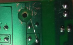
Anyway I've attached a thumbnail to show how I would fix that cut in the board. I've placed a white mark where I would do the work... clean the foil on both sides of the scratch, tin it, lay in a piece of wire and solder it down then trim the wire ends... that should do it.
Anyway I've attached a thumbnail to show how I would fix that cut in the board. I've placed a white mark where I would do the work... clean the foil on both sides of the scratch, tin it, lay in a piece of wire and solder it down then trim the wire ends... that should do it.
Attachments
Best I can find out, the model was introduced in 2004 ... Unless we have and extreme environment issue, I doubt component aging or tarnishing is much of an issue...
Personally I think the issue is a botched prior attempt at repair...
That could easily be the case.
That helps, thanks. I'm more familiar in the digital domain. I use a similar circuit in my housekeeping circuit but it triggers an optocoupler and is only for voltage loss. I measure voltage drop on emitter resistors for current sensing again with an optocoupler. Simple inputs to decode with a microcontroller.
Here's the data sheet for that chip, such as it is...
It's not really digital, just some clever analog stuff.
Attachments
That helps, thanks. I'm more familiar in the digital domain. I use a similar circuit in my housekeeping circuit but it triggers an optocoupler and is only for voltage loss. I measure voltage drop on emitter resistors for current sensing again with an optocoupler. Simple inputs to decode with a microcontroller.
AND ... a much better way of doing things.
LOL! Apologies. It's particularly hard when reading the initial post from the e-mail.
So, good voltages there. It goes to show I still have a ton to learn from both examining the physical side of things and following schematics, but... There is still something funky with J2. I took out the LED board after checking the voltages, lo and behold... Blue LED flickers. Traced it back to my old friend J2. I'm going to disassemble the female completely, examine the innards and see if there's a bad crimp, clean the contacts inside, and put it back together.
Sheesh!
Thank you very, very much.
This is a perfectly sensible thing to do...
When you reassemble it take each wire seperately and wiggle it a bit, if it trigger protection you've got an actual break in the wire, not a connector problem.
Odds are that connector is what triggered this entire situation.
Last edited:
You guys are amazing. I am not only trying to just "do the work" on the board, but follow along with the logic re: how the circuit is intended to function and what may cause it to flake out.
So, at the moment. I have the bridge pad to pad vs. the permanent repair on the "cut". I will fix that once we figure out what else may be at issue. Should not take long. However, we have good continuity now, and I'd hate to introduce yet another error or compounding factor, should I goof the repair. So, I'll always follow the best advice of experts, but the little bridge is sound, and is what got us going, so I'd prefer to hold off on "repairing it better". I understand that it's not the best permanent solution, but while we're still troubleshooting, "if it ain't broke.. don't break it" 😀
re: J2. I have that thing solid as a rock at the moment. At least I think I do. Not saying it could not have an underlying issue. What is still puzzling (to me) is the issue with the power LED. Still will not engage again. That is a head-scratcher, but for another time. No amount of wiggling will cause the protection LEDs to flutter after my "reinforcements" and cleaning. I'll definitely consider soldering the leads directly to the board, but again, everything for the moment indicates a reliable connection. As an example, if we were getting intermittent drop outs from J2, I would generally think it would continue throughout operation and cause the circuit to go back into protection at some point. However, once the amp leaves protection after power up, it stays functioning for hours.
re: preventing a catastrophic short to ground - I put in a temporary, but effective stop-gap until I can find some very thin washers that allow the board not to flex when the one point that should be grounded is in place and also won't stress the legs or the part for the rectifier (which is bolted to the chassis for heat-sinking).
-------------
New information.
I am not sure if this would help AT ALL, but I'm always curious. We seem to be focused on Pin 1. So, I did a bit of an experiment to see what kind of fluctuations happen at that pin. I turned off the amp and let it sit for a few minutes to drain caps etc.
Fired it back up.
Starts off ~(-)60mV
Over several minutes the voltage slowly climbs to very, very close to (-)160mV. Click.
At the click - the voltage immediately drops to (-)150 or so while the relay is engaged.
Click - Relay very quickly disengages.
Voltage immediately shows (-)162ish
Relay Clicks... Voltage drops ... relay disengages.
This occured 5-6 times over the course of a minute or so, until the voltage with the relay not engaged was about (-)170mV then it dropped one more time to just about (-)159mV. Then it picked back up and stayed engaged.
So, to my naive brain... It seems the voltage at Pin 1 needs to be roughly (-)160mV or higher (lower) to trigger the relay.
After another 5mins or so, the voltage at pin 1 seems to cap out at about (-)385mV After 10mins or so, the voltage is (-)428mV. After 30mins or so, the voltage is (-)-440mV. Still not in protection and has not switched into protection.
In the multiple times I've measured at that pin, I have not seen a spike or dramatic drop in voltage that would indicate a disconnection at J2. The only times I saw that behavior was when I was intentionally poking at things, which.. I know I'm not supposed to do, but it's how mechanical reliability issues and bad joints have revealed themselves to me in the past... so kind of like the quote in Hunt for Red October... when I get confused, I kind of run home to mama.
So... something... is slowly allowing the negative voltage to climb at pin 1 from (-)60mV or until the relay starts to to engage, drop, and re-engage until it does not drop below (over) (-)160. The voltage continues to climb (drop) for a while until it seems to reach near equilibrium at around (-)450mV or so. I'll continue to monitor it to see if it continues to rise (drop).
Is it completely absurd to wonder what is slowing the negative voltage change at that pin? I'm often out in left field, but in my current practice, I observe and try to notice trends ... then I can see what controls those trends... May be a crazy approach, but I'm still trying to grasp the schematic on a more intelligent level.
Side note... How does one refer to a voltage change from (-)60 to (-)400? Is that a "reduction"? Seems the potential has increased, so the voltage has increased, but just reading it from a polarity standpoint... looks like a mathematical decrease.
Last edited:
You guys are amazing. I am not only trying to just "do the work" on the board, but follow along with the logic re: how the circuit is intended to function and what may cause it to flake out.
That's why I spent so much time trying to explain things.
It's a truly sad fact that in the entire history of mankind, nobody has ever solved a problem they don't understand. You'd be amazed how many repairs (and other solutions) are pure accidents.
So, at the moment. I have the bridge pad to pad vs. the permanent repair on the "cut". I will fix that once we figure out what else may be at issue.
Either way is fine... I just prefer to fix the foil, in case I have to solder on the points again.
but while we're still troubleshooting, "if it ain't broke.. don't break it" 😀
ROFL ...
re: J2. I have that thing solid as a rock at the moment. At least I think I do. Not saying it could not have an underlying issue. What is still puzzling (to me) is the issue with the power LED. Still will not engage again.
Separate issue. I have a couple of notes here on things I want to revisit once it is working and stable. That's on the list.
That is a head-scratcher, but for another time. No amount of wiggling will cause the protection LEDs to flutter after my "reinforcements" and cleaning. I'll definitely consider soldering the leads directly to the board, but again, everything for the moment indicates a reliable connection.
It is best to leave the connector in there, in case of future repairs or replacement of that board. Soldering directly is a last resort.
You might consider very carefully and lightly tinning the pins that stand up from the board in the male side of that connector. The slight increase in size will make a much better connection.
As an example, if we were getting intermittent drop outs from J2, I would generally think it would continue throughout operation and cause the circuit to go back into protection at some point. However, once the amp leaves protection after power up, it stays functioning for hours.
You are correct. It should take only a few missing half cycles to trigger protection...
re: preventing a catastrophic short to ground - I put in a temporary, but effective stop-gap until I can find some very thin washers that allow the board not to flex when the one point that should be grounded is in place and also won't stress the legs or the part for the rectifier (which is bolted to the chassis for heat-sinking).
Even putting a bit of tape on those corners with a hole punched in to allow the bolt through will work. We're worried about contact, not arcing.
New information.
I am not sure if this would help AT ALL, but I'm always curious. We seem to be focused on Pin 1. So, I did a bit of an experiment to see what kind of fluctuations happen at that pin. I turned off the amp and let it sit for a few minutes to drain caps etc.
Fired it back up.
Starts off ~(-)60mV
Over several minutes the voltage slowly climbs to very, very close to (-)160mV. Click.
At the click - the voltage immediately drops to (-)150 or so while the relay is engaged.
Click - Relay very quickly disengages.
Voltage immediately shows (-)162ish
Relay Clicks... Voltage drops ... relay disengages.
This occured 5-6 times over the course of a minute or so, until the voltage with the relay not engaged was about (-)170mV then it dropped one more time to just about (-)159mV. Then it picked back up and stayed engaged.
So, to my naive brain... It seems the voltage at Pin 1 needs to be roughly (-)160mV or higher (lower) to trigger the relay.
After another 5mins or so, the voltage at pin 1 seems to cap out at about (-)385mV After 10mins or so, the voltage is (-)428mV. After 30mins or so, the voltage is (-)-440mV. Still not in protection and has not switched into protection.
In the multiple times I've measured at that pin, I have not seen a spike or dramatic drop in voltage that would indicate a disconnection at J2. The only times I saw that behavior was when I was intentionally poking at things, which.. I know I'm not supposed to do, but it's how mechanical reliability issues and bad joints have revealed themselves to me in the past... so kind of like the quote in Hunt for Red October... when I get confused, I kind of run home to mama.
So... something... is slowly allowing the negative voltage to climb at pin 1 from (-)60mV or until the relay starts to to engage, drop, and re-engage until it does not drop below (over) (-)160. The voltage continues to climb (drop) for a while until it seems to reach near equilibrium at around (-)450mV or so. I'll continue to monitor it to see if it continues to rise (drop).
Is it completely absurd to wonder what is slowing the negative voltage change at that pin? I'm often out in left field, but in my current practice, I observe and try to notice trends ... then I can see what controls those trends... May be a crazy approach, but I'm still trying to grasp the schematic on a more intelligent level.
Side note... How does one refer to a voltage change from (-)60 to (-)400? Is that a "reduction"? Seems the potential has increased, so the voltage has increased, but just reading it from a polarity standpoint... looks like a mathematical decrease.
OMG... he's gone orbital... 😀
If the amp is stable, you've fixed it...
Technician's rules...
1) If it ain't broke, don't fix it.
2) If it is broke know when to stop fixing it.
3) (thanks to you) If it ain't broke, don't break it.
I'd say that so long as the main system is working and stable this is a great time to declare victory.
That said, there are a couple of mop up checks I would like you to perform... but first you need to get it hooked up someplace and run it for a while with real music and real speakers... if it runs for a few hours at reasonable volume without problems we can look at the clean up checks after.
I worked at Alesis when the RA 150 came out. That amp was not designed by Alesis engineers. It was an OEM thing ordered drop shipped from some company in China. I can't remember the manufacturing company name, like Audio King or some such genericness. When I saw the schematic I was scratching my head. I just remember it was a convoluted design. It never sold well so there weren't many to fix; good thing for me because I was the main repair tech for the RA 100.
I worked at Alesis when the RA 150 came out. That amp was not designed by Alesis engineers. It was an OEM thing ordered drop shipped from some company in China. I can't remember the manufacturing company name, like Audio King or some such genericness. When I saw the schematic I was scratching my head. I just remember it was a convoluted design. It never sold well so there weren't many to fix; good thing for me because I was the main repair tech for the RA 100.
Thanks for that.
Looking at the schematic I could see some real iffy design points ... like using zener regulators for op-amps and using one of the DC offset inputs on the TA7317 as a thermal detector. The overcurrent detector, which was the problem here, probably should have been left out, freeing pin 1 for a better thermal detector design.
But it is what it is... and now it's working.
It has been a rather convoluted repair, that's for sure. I was hoping to first solve the relay problem, then walk along the various protection inputs to find which one was triggering it... I had two prime candidates in mind... mismatched thermistors or that AC detector circuit. Turns out our friend got there before I did... (Gotta love it when the student gets ahead of the teacher.)
That's why I spent so much time trying to explain things.
It's a truly sad fact that in the entire history of mankind, nobody has ever solved a problem they don't understand. You'd be amazed how many repairs (and other solutions) are pure accidents.
Either way is fine... I just prefer to fix the foil, in case I have to solder on the points again.
Your explanations are exceptional. I mean this sincerely, it's people such as yourself that keep me enthusiastic about the hobby I've only recently begun to pursue. I started with "build cool stuff", now I'd like to understand a bit more about how those things work and why the brilliant minds that design some of my gear made the choices they made. I love music, but I never understood electronics at any real level. I only understood what the magazines told me. I can barely comprehend (okay, I sort of get it) Class A bias etc.
But, in order to understand any of that, I need to go back to first principles. I can repeat certain things by rote, but I can't say that I "understand them" (yet).
Separate issue. I have a couple of notes here on things I want to revisit once it is working and stable. That's on the list.
Perfect. The two things I have on the list for "ideal" operation vs. "working" are:
1) Get it out of protection sooner after initial power up. 5 mins or more is not ideal. 20s or less is what the operator's manual states, if I recall.
2) The power LED. I'd rate this pretty low on the list, but I'd like to do it.
It is best to leave the connector in there, in case of future repairs or replacement of that board. Soldering directly is a last resort.
Agreed.
Great idea!You might consider very carefully and lightly tinning the pins that stand up from the board in the male side of that connector. The slight increase in size will make a much better connection.
I'm capturing that just to show my wife that on rare occasion I can be correct. 😀You are correct. It should take only a few missing half cycles to trigger protection...
Even putting a bit of tape on those corners with a hole punched in to allow the bolt through will work. We're worried about contact, not arcing.
 That's exactly what I did. Two layers of blue painter's tape.
 OMG... he's gone orbital... 😀
If the amp is stable, you've fixed it...
Technician's rules...
1) If it ain't broke, don't fix it.
2) If it is broke know when to stop fixing it.
3) (thanks to you) If it ain't broke, don't break it.
I'd say that so long as the main system is working and stable this is a great time to declare victory.
I may have declared a major battle won earlier... 😀
That said, there are a couple of mop up checks I would like you to perform... but first you need to get it hooked up someplace and run it for a while with real music and real speakers... if it runs for a few hours at reasonable volume without problems we can look at the clean up checks after.
I've been jammin' since the previous post... so... 8:34GMT until 9:34GMT. Go figure... an hour almost on the dot.
I worked at Alesis when the RA 150 came out. That amp was not designed by Alesis engineers. It was an OEM thing ordered drop shipped from some company in China. I can't remember the manufacturing company name, like Audio King or some such genericness. When I saw the schematic I was scratching my head. I just remember it was a convoluted design. It never sold well so there weren't many to fix; good thing for me because I was the main repair tech for the RA 100.
Wow! Small world. Thanks for chiming in. FWIW, my buddy loves this amp. He got it in 2001 at a Guitar Center. I suppose that's why I've gone to such trouble to get it fixed for him. That, and.... 1) He was going to throw it away, and I hate "e-waste" 2) I want my SissySIT back that I loaned him until I get this back to him. 😀
Your explanations are exceptional. I mean this sincerely, it's people such as yourself that keep me enthusiastic about the hobby I've only recently begun to pursue. I started with "build cool stuff", now I'd like to understand a bit more about how those things work and why the brilliant minds that design some of my gear made the choices they made. I love music, but I never understood electronics at any real level. I only understood what the magazines told me. I can barely comprehend (okay, I sort of get it) Class A bias etc.
But, in order to understand any of that, I need to go back to first principles. I can repeat certain things by rote, but I can't say that I "understand them" (yet).
There are a ton of websites explaining amplifier classes. If you like I can help you in a separate thread or in PMs.
Perfect. The two things I have on the list for "ideal" operation vs. "working" are:
1) Get it out of protection sooner after initial power up. 5 mins or more is not ideal. 20s or less is what the operator's manual states, if I recall.
2) The power LED. I'd rate this pretty low on the list, but I'd like to do it.
Yes... 5 minutes is riduculous. Added to my list.
I also have the power led, the voltages on Z1 and Z2 and a couple of other minor checks I want you to do. But that can wait until it passes the in-use test.
As long as it doesn't become conductive when wet, you're all set.
I've been jammin' since the previous post... so... 8:34GMT until 9:34GMT. Go figure... an hour almost on the dot.
Ok... well, enjoy it for tonight. If there are no problems, we can start on the cleanup list tomorrow.
There are a ton of websites explaining amplifier classes. If you like I can help you in a separate thread or in PMs.
Thank you, very much. I should have been more clear. I think I have a firm grasp on the differentiations of the "Class Designations" even though they are often argued about and potentially misunderstood. i.e. are all push-pull amplifiers Class A-B? Where I am still a bit foggy is still around the term bias, and how that bias current relates to not only "keeping the device always powered on" as an example for Class A, but how that relates to terms I have yet to understand like Vgs, Idss etc. etc. etc.
Also... as a side note... trusted references on the great WWW are tough. In my field, I see a tremendous amount of information that is not only incorrect, it borders on misleading to the level of FTC violations (IMO). Marketing garble overtakes real engineering specs. /RANT
Ok... well, enjoy it for tonight. If there are no problems, we can start on the cleanup list tomorrow.
Definitely - time for a bit more music and a beer.
I hope you enjoy your evening also.

Thank you, very much. I should have been more clear. I think I have a firm grasp on the differentiations of the "Class Designations" even though they are often argued about and potentially misunderstood. i.e. are all push-pull amplifiers Class A-B?
Nope ... some are class B, some class C and some are (stupidly) class A.
Where I am still a bit foggy is still around the term bias, and how that bias current relates to not only "keeping the device always powered on" as an example for Class A, but how that relates to terms I have yet to understand like Vgs, Idss etc. etc. etc.
Complex topic... one that we may have to broach here, depending on the in-use test.
Also... as a side note... trusted references on the great WWW are tough. In my field, I see a tremendous amount of information that is not only incorrect, it borders on misleading to the level of FTC violations (IMO). Marketing garble overtakes real engineering specs. /RANT
As a friend of mine points out... "It's the most dishonest place that never existed".
I hope you enjoy your evening also.
Yes sir.
Last edited:
Cleaning up
@itsallinmyhead
Just before I shut everything down for the night there are a few things I would like you to check for me, assuming of course that all went well in the listening test.
1) The voltage on the relay.
This will mean reading the voltages on both ends of D403 to ground (yet again) with the amp in ready condition. As you know this diode is across the relay coil so the difference in voltage will tell me the voltage on the relay coil. The relay is designed for 12 volts but as you know it pulls in on 9 volts. So we probably want 10 or 11 volts on the coil for maximum lifetime. If it is higher than 12 we will need to do a modification to correct it. (Not all relay coils are the same)
2) OpAmp voltage regulator
I need voltage readings, not in protection mode, from the junctions of Z1/R401 and Z2/R402. These provide regulated voltage for the opamps on the amplifier and driver boards. Per the schematic they should be with in a few tiny steps of +15 and -15 respectively. If they are off by much we will design a modification to fix it. Note that I held off on this until we got the amp out of protection, because these voltages can be affected by load and can cause increased instability in the amplifiers, which might affect the turn on delay.
3) The power led.
Look at the schematic, the power LED is simply in series with a resistor. Follow the voltage... Check the voltage at pin2 of J8 on the display board (orange wire). It should be about 11.5 volts. Next check the voltage on both sides of LED1, the difference should about 1.8 or 2.0 volts, then the voltage at R304 should be about 10.5 volts... Don't be surprised if your probe makes it light up... We're looking for a bad connection. Depending where the voltage drops out, we'll get a repair going.
4) The long turn on protection delay
It is likely that correcting #2 will have an effect on the turn on delay. Any inequality in the +15 and -15 volt supplies will increase the initial instability of the amplifiers, so we worry about this after the opamp regulator issue is addressed. This will be something of a slow process as it will involve monitoring the TA7317 inputs at power on, one at a time, to see which one doesn't settle down right away. Once we know which is the trouble maker, we'll work out a fix.
Post back when you have the initial readings for me
Last edited:
@itsallinmyhead
Just before I shut everything down for the night there are a few things I would like you to check for me, assuming of course that all went well in the listening test.
1) The voltage on the relay.
This will mean reading the voltages on both ends of D403 to ground (yet again) with the amp in ready condition. As you know this diode is across the relay coil so the difference in voltage will tell me the voltage on the relay coil. The relay is designed for 12 volts but as you know it pulls in on 9 volts. So we probably want 10 or 11 volts on the coil for maximum lifetime. If it is higher than 12 we will need to do a modification to correct it. (Not all relay coils are the same)
Cathode Side - 15.87
Anode Side - 1.195
So - 14V68 across. A tad high, but my mains runs at a steady 120 vs. 110/115. Not sure what my buddy's runs at.
To be fair, I'm not terribly worried about coil life. Current coil is 18+ years old with countless hours. I can swap the relay to the "new" one now that I know what was causing it to not pull in. I think I read a max voltage on the specs of much higher if there's a concern re: life due to a higher voltage. However, if we can tweak an appropriate resistor, I'd certainly be willing to do that for my friend.
2) OpAmp voltage regulator
I need voltage readings, not in protection mode, from the junctions of Z1/R401 and Z2/R402. These provide regulated voltage for the opamps on the amplifier and driver boards. Per the schematic they should be with in a few tiny steps of +15 and -15 respectively. If they are off by much we will design a modification to fix it. Note that I held off on this until we got the amp out of protection, because these voltages can be affected by load and can cause increased instability in the amplifiers, which might affect the turn on delay.
Z1/R401: +17V2
Z2/R402: -16V4
Those could stand to be a bit more balanced. Those are both in the area of the amp that was darkened by the severe heat. Those components look a bit scarred, particularly Z1 and Z2. Shame I already placed my parts order, but I may have some zeners laying around if it comes to that. I can cross reference values.
3) The power led.
Look at the schematic, the power LED is simply in series with a resistor. Follow the voltage... Check the voltage at pin2 of J8 on the display board (orange wire). It should be about 11.5 volts. Next check the voltage on both sides of LED1, the difference should about 1.8 or 2.0 volts, then the voltage at R304 should be about 10.5 volts... Don't be surprised if your probe makes it light up... We're looking for a bad connection. Depending where the voltage drops out, we'll get a repair going.
Pin 2 J8A: 12V35 on PSU side
Pin 2 J8B: 12V35 on LED board side.
Touched up solder on the back side of the connection board (J8B) and also the leads to the LED itself. We have light.
Turns out that when I was jiggling J2, I was also jiggling J8. The wiring harnesses were zip tied together. I need that facepalm emoji again. Sorry for that wild goose chase re: the transformer leads to the PSU board. I'm still glad I went through the entire harness and beefed it up after so many disconnects / re-connects, but likely unnecessary.
4) The long turn on protection delay
It is likely that correcting #2 will have an effect on the turn on delay. Any inequality in the +15 and -15 volt supplies will increase the initial instability of the amplifiers, so we worry about this after the opamp regulator issue is addressed. This will be something of a slow process as it will involve monitoring the TA7317 inputs at power on, one at a time, to see which one doesn't settle down right away. Once we know which is the trouble maker, we'll work out a fix.
Post back when you have the initial readings for me
I've had the amp on consistently since 8:34GMT. Seems stable 😀
Oddly, when I had the amp off for several minutes to remove the LED board and touch it up, I expected the caps to drain, and thus for it to take a while to leave protection upon powering back up. It popped right out of protection.
I'm going to leave the amp off over night. That may tell us whether thermals and/or initial electrical stability are potential culprits for the slower start up times earlier.
I'll look forward to some ideas. Initially mine are to remove and clean up Z1 and Z2 along with the associated resistors. I'll do a bit of research on how to properly measure and check a Zener.
Last edited:
- Home
- Amplifiers
- Solid State
- Repair of Alesis RA150