To be fair, I'm not terribly worried about coil life. Current coil is 18+ years old with countless hours. I can swap the relay to the "new" one now that I know what was causing it to not pull in.
Yes put in the new relay and take the readings again.
You are going to have to change R417 anyway... that thing looks like someone tried to skin it... it has to be replaced. So, while we're at it why not work out and put in the right value?
Z1/R401: +17V2
Z2/R402: -16V4
Those could stand to be a bit more balanced. Those are both in the area of the amp that was darkened by the severe heat. Those components look a bit scarred, particularly Z1 and Z2.
Right off ... This is a stupid place to use zener regulators.
The voltages you posted tell me those diodes have already failed. Catastrophic failure won't be very far down the road. If one or both zeners go open, it will put bulk supply (40 volts) into those opamps and it will destroy every single one of them, effectively killing the amp for good.
Replace Z1 and Z2 with 1N5351 diodes. These are 14 volt, 5 watt parts that will never fail in that position.
Replace R401 and R402 with 560 ohm 2 watt parts.
And no junk box parts, get new ones. They're not that expensive and this is a critical circuit that has to work right.
This should end you up with 14 volts on each supply so age creep can land them at 15, 10 years from now.
When you install the new parts, do the initial test with J6 and J4 unplugged to protect the op-amps, the amp will likely stay in protection mode. Once you confirm the voltages, shut down and plug the cables back in. From there it should operate normally.
Shame I already placed my parts order, but I may have some zeners laying around if it comes to that. I can cross reference values.
Sorry to say but I think you jumped the gun on that one.
Touched up solder on the back side of the connection board (J8B) and also the leads to the LED itself. We have light.
Well, that's fixed... good work.
I've had the amp on consistently since 8:34GMT. Seems stable 😀
Oddly, when I had the amp off for several minutes to remove the LED board and touch it up, I expected the caps to drain, and thus for it to take a while to leave protection upon powering back up. It popped right out of protection.
How long did it take?
The part values on the timing input to U1 (pin 8) look like about 10 seconds.
I'm going to leave the amp off over night. That may tell us whether thermals and/or initial electrical stability are potential culprits for the slower start up times earlier.
Yes it will ... but if it's not reliably under, lets say, 20 seconds, we're going to have to troubleshoot the inputs to U1, to confirm and correct the cause.
Last edited:
Had to get a few things done this morning before DIY. I won't be able to dedicate quite as much time during the week. 😀
You were asking re: start up times. It took 15 mins (roughly) this morning for the (-)160mV or so to get to pin 1. Click. Then again, roughly a minute of clicking in and out of protection until we got a stable (-)160 or more voltage at pin 1. Now that you've helped me understand Z1, Z2 and associated parts - it leads me to think that those heat damaged parts are in large part the contributors to the "real" fault / slow start up.
New Readings at D403 after new relay install.
1V17
18V0
So, 16V83 across
All noted with thanks. Parts in the cart.
Makes perfect sense. Will do.
Not a worry. I'm always ordering something. Once we finalize what I need for this repair, I can have all the parts by end of week, no problems.
Agreed. My guess is after we replace those suspect parts in the area that saw all the thermal stress, we will be well on our way, if not complete.
Makes perfect sense. I put in the new relay. Did the quick short test at pin 1. Snaps right in.Yes put in the new relay and take the readings again.
You are going to have to change R417 anyway... that thing looks like someone tried to skin it... it has to be replaced. So, while we're at it why not work out and put in the right value?
You were asking re: start up times. It took 15 mins (roughly) this morning for the (-)160mV or so to get to pin 1. Click. Then again, roughly a minute of clicking in and out of protection until we got a stable (-)160 or more voltage at pin 1. Now that you've helped me understand Z1, Z2 and associated parts - it leads me to think that those heat damaged parts are in large part the contributors to the "real" fault / slow start up.
New Readings at D403 after new relay install.
1V17
18V0
So, 16V83 across
Right off ... This is a stupid place to use zener regulators.
The voltages you posted tell me those diodes have already failed. Catastrophic failure won't be very far down the road. If one or both zeners go open, it will put bulk supply (40 volts) into those opamps and it will destroy every single one of them, effectively killing the amp for good.
Replace Z1 and Z2 with 1N5351 diodes. These are 14 volt, 5 watt parts that will never fail in that position.
Replace R401 and R402 with 560 ohm 2 watt parts.
And no junk box parts, get new ones. They're not that expensive and this is a critical circuit that has to work right.
This should end you up with 14 volts on each supply so age creep can land them at 15, 10 years from now.
All noted with thanks. Parts in the cart.
When you install the new parts, do the initial test with J6 and J4 unplugged to protect the op-amps, the amp will likely stay in protection mode. Once you confirm the voltages, shut down and plug the cables back in. From there it should operate normally.
Makes perfect sense. Will do.
Sorry to say but I think you jumped the gun on that one.
Not a worry. I'm always ordering something. Once we finalize what I need for this repair, I can have all the parts by end of week, no problems.
It went out of protection almost immediately. Leads me to believe thermals. The caps would have been fully drained after a few minutes, but the board may have still been "warm". After we change out all affected parts, it'll be a moot point.How long did it take?
The part values on the timing input to U1 (pin 8) look like about 10 seconds.
Yes it will ... but if it's not reliably under, lets say, 20 seconds, we're going to have to troubleshoot the inputs to U1, to confirm and correct the cause.
Agreed. My guess is after we replace those suspect parts in the area that saw all the thermal stress, we will be well on our way, if not complete.
Had to get a few things done this morning before DIY. I won't be able to dedicate quite as much time during the week. 😀
This has been a bit crazy ... but strangely enough I've been looking forward to the nest installment.
Makes perfect sense. I put in the new relay. Did the quick short test at pin 1. Snaps right in.
You really shouldn't use that grounding test as a routine thing. I proposed it as a one time test and even warned you that it wasn't a safe thing to do. One of these times it's going to backfire on you and it could leave you with a cooked protection chip... and they don't make them anymore.
Shorting things out is not a routine diagnostic and it most certainly is not a safe thing to do.
You were asking re: start up times. It took 15 mins (roughly) this morning for the (-)160mV or so to get to pin 1. Click. Then again, roughly a minute of clicking in and out of protection until we got a stable (-)160 or more voltage at pin 1.
It may not be only pin 1 that is our problem. Although touching it does seem to get the amp going pretty quick. I'll look at the schematic again and see what I can come up with as far as monitoring and testing goes... In the mean time... please stop shorting stuff out.
Now that you've helped me understand Z1, Z2 and associated parts - it leads me to think that those heat damaged parts are in large part the contributors to the "real" fault / slow start up.
If the op amps are starting up with an offset because of unequal/incorrect supplies it may well be some time before the amplifiers reach 0 DC offset, which would delay the startup. But there might be other causes too...
New Readings at D403 after new relay install.
1V17
18V0
So, 16V83 across
So we're looking at 17 volts across the relay and 28 (45-17) on R417 ... That's a bit much.
R417 is currently 680 ohms
The relay coil is ~380 ohms
We're looking for about 12v / 380 == 30 ma of current.
With the relay at 12 volts we're looking for 45 - 12 == 33 volts on R417.
Ohms law tells us that 33v / .030a == 1100 ohms.
1100 ohms is not a standard value, so I would go with 1k (1000 ohms).
So you want to replace R417 with a 1k 2 watt resistor.
That should put about 12.5 volts on the relay which is much safer.
It went out of protection almost immediately. Leads me to believe thermals. The caps would have been fully drained after a few minutes, but the board may have still been "warm". After we change out all affected parts, it'll be a moot point.
The only thermal measuring done is for the thermistors on the heatsinks in the power amps. The actual temperature of the power supply board or it's parts is not monitored.
The most likely culprit is the overcurrent sensor, because of how it responds when poked. That it still goes into and out of protection after that probably indicates a problem in that circuit but there may be other possibilities.
I would not suggest just randomly changing everything... this is a mistake many technicians make. If it works after changing 20 parts you won't know what the problem was or how to trouble shoot it if you come across it again. In effect this tactic of "replace everything" amounts to self-sabotage since you don't learn anything from it.
Agreed. My guess is after we replace those suspect parts in the area that saw all the thermal stress, we will be well on our way, if not complete.
We'll see...
This has been a bit crazy ... but strangely enough I've been looking forward to the nest installment.
Agreed. I would have handed the amp back to my friend quite some time ago had this not turned into a quite enjoyable learning experience. Again, you've got the patience of Job. I hope to be able to pay this kindness forward some day.
Noted with thanks - No more shorting. Confirmed relay works in the circuit, so no need.You really shouldn't use that grounding test as a routine thing. I proposed it as a one time test and even warned you that it wasn't a safe thing to do. One of these times it's going to backfire on you and it could leave you with a cooked protection chip... and they don't make them anymore.
Shorting things out is not a routine diagnostic and it most certainly is not a safe thing to do.
It may not be only pin 1 that is our problem. Although touching it does seem to get the amp going pretty quick. I'll look at the schematic again and see what I can come up with as far as monitoring and testing goes... In the mean time... please stop shorting stuff out.
Sorry, I meant to convey that whatever voltage is hitting pin one, that odd voltage of -160mV, seems to be a constant measurement where it triggers. Agreed that the root cause of what controls that voltage is the culprit... maybe...
If the op amps are starting up with an offset because of unequal/incorrect supplies it may well be some time before the amplifiers reach 0 DC offset, which would delay the startup. But there might be other causes too...
I think I grasp that. I thought that was controlled by the Z1 and Z2. So my error in thinking replacing those and getting a stable +- 14V would stabilize this particular issue and thus... may... get the amp out of protection faster. I'll review again.
In the cart.So we're looking at 17 volts across the relay and 28 (45-17) on R417 ... That's a bit much.
R417 is currently 680 ohms
The relay coil is ~380 ohms
We're looking for about 12v / 380 == 30 ma of current.
With the relay at 12 volts we're looking for 45 - 12 == 33 volts on R417.
Ohms law tells us that 33v / .030a == 1100 ohms.
1100 ohms is not a standard value, so I would go with 1k (1000 ohms).
So you want to replace R417 with a 1k 2 watt resistor.
That should put about 12.5 volts on the relay which is much safer.
The only thermal measuring done is for the thermistors on the heatsinks in the power amps. The actual temperature of the power supply board or it's parts is not monitored.
The most likely culprit is the overcurrent sensor, because of how it responds when poked. That it still goes into and out of protection after that probably indicates a problem in that circuit but there may be other possibilities.
I would not suggest just randomly changing everything... this is a mistake many technicians make. If it works after changing 20 parts you won't know what the problem was or how to trouble shoot it if you come across it again. In effect this tactic of "replace everything" amounts to self-sabotage since you don't learn anything from it.
My lack of proper terminology strikes again. I was attempting to convey that my theory was that certain parts around the Z1, Z2, R401, R402 area may behave differently after getting hot. Apologies for the confusion, I was not referring to the thermistors on the heatsinks or the thermal check through U1.
Definitely not planning on changing everything. I like to change one part (or an appropriate set of part complements) at a time. In my work and hobbies, one variable at a time is the rule not the exception.
I'll report back after the parts arrive, and I get the first ones changed out.
Agreed. I would have handed the amp back to my friend quite some time ago had this not turned into a quite enjoyable learning experience. Again, you've got the patience of Job. I hope to be able to pay this kindness forward some day.
Well, lets get it finished up first ...
Noted with thanks - No more shorting. Confirmed relay works in the circuit, so no need.
Good.
Sorry, I meant to convey that whatever voltage is hitting pin one, that odd voltage of -160mV, seems to be a constant measurement where it triggers. Agreed that the root cause of what controls that voltage is the culprit... maybe...
I'm working on a post, in another tab, to address that. It'll be up in an hour or so.
I think I grasp that. I thought that was controlled by the Z1 and Z2. So my error in thinking replacing those and getting a stable +- 14V would stabilize this particular issue and thus... may... get the amp out of protection faster. I'll review again.
If you follow the schematic into the driver and power amp boards, you will find those opamps are on the input to the amplifier and in the feedback path. They are AC coupled with the circuit, so the voltage on their outputs controls the DC offset of the amplifier until those capacitors charge ... if it's not right or if compensation takes time, there will be a trigger at pin 2 of the protection chip until it settles down.
My lack of proper terminology strikes again. I was attempting to convey that my theory was that certain parts around the Z1, Z2, R401, R402 area may behave differently after getting hot.
They probably do. This is why the change from 1 watt to 5 watt zeners. They will be less prone to heat up with the current they're sinking and should be more thermally stable.
Definitely not planning on changing everything. I like to change one part (or an appropriate set of part complements) at a time. In my work and hobbies, one variable at a time is the rule not the exception.
Excellent. But it is a mistake a lot of beginning technicians make, so I thought I should mention it.
I'll report back after the parts arrive, and I get the first ones changed out.
Okey dokey ... In the mean time we can probe that AC detector and see if we can't spot the problem there...
The AC/Current detector
@itsallinmyhead
Lets take a look at that AC detector circuit...
But first there is something we need to know about your multimeter. I need you to put it on the AC scale and hook up to a battery. You will need to test this in both normal and reversed polarity. What we are trying to discover is if the meter ignores DC when on the AC scale... if it does it will read practically 0 in both directions. If not at least one direction will read the battery.
If it doesn't ignore DC we can make ignore DC by putting a low value capacitor in series with the positive probe... a .1 uf ceramic cap should serve nicely. In this case the readings won't be as accurate but that's not going to be a problem. I generally just wrap one lead of the cap around the meter's probe wrap it tightly with a bit of tape and use the other lead as my test probe... Verify this by testing the battery again you should see nearly 0 after a second or two to settle in. We'll use this for the AC scale measurements, but remove it for DC measurements.
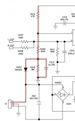
The way this circuit operates is that D402 is tied to one side of the AC input from the transformer at pin1 of J2. It samples this AC voltage and rectifies it to pulsing DC. This pulsing DC is smoothed to a steady DC voltage by C413. This is a negative voltage that is applied to the voltage divider chain of R412 and R409, the junction of which feed the input to the protection chip. At pin 1 of U1 we want a negative voltage when things are operating normally. But if the AC drops out or falls off significantly by loading the transformer, the voltage on C413 will move more positive, changing the voltage at the junction of R409 and R412. If this voltage goes above about .5 volts protection is triggered.
Failure modes in this circuit are that the D402 is not correctly sampling the AC input, C413 is not filtering out AC or R409 is not providing a negative voltage to the input.
So here goes...
It doesn't matter if the amp is in protection or not.
The attached thumbnail shows you the parts we are going to be working with, highlighted in red.
As a preparatory step you should examine the foil and solder for good connections... we already got caught out on that one on the relay, so lets go there first with this.
Test 1 ... Using the AC scale get a reading from pin 1 of J2. It should be somewhere around 30 or 31 volts and it should be stable, varying by no more than half a volt when the amplifier is quiet.
Test 2 ... Repeat the reading from the cathode (ring) of D402. It should show the same voltage with equal stability.
While you are on this point, gently wiggle and tug the wire from pin 1 to the transformer, moving very slowly to see if there are any drop outs in the voltage. If there are, it would indicate a connector problem... broken wire, intermittent contact, bad solder... You will need to fix this before moving on.
Test 3 ... On your DC scale take a reading from the anode of D402. This should read about -40 volts and it should be fairly stable.
If you are reading less than that, shut everything down, lift one leg of D402 and test it on your Diode scale. It could be either open or shorted. In either of those events replace D402, observing the polarity in the schematic, before moving on.
Now take a look at the schematic...
The anode of D402 feeds C413, which will smooth the rectified AC from D402. In other words, at this point the AC is gone and only the rectified DC voltage remains.
Test 4 ... on your AC scale (with the isolation cap, if needed) take a reading from the anode of D402. This will tell us the state of C413. if all is good you should not read very much AC there at all, maybe a volt or so.
If you do get strong AC you will need to replace C413 and get this reading down before moving on. If you need to change the part, I would suggest staying with the designated 1uf 100v part, no more than 2.2uf 100v. Electrolytic caps should be fine here. Remember to observe polarity when installing, the cap has it's + pole to ground.
Once we have stable DC at D402/R410, we can move on to the voltage divider formed by R412 and R409. Using ohm's law we can figure out what the voltage here should be ...
We should have ~ -40 volts at one end of the chain and +3 (the protection chip's supply voltage) at the other ... so 43 volts across the two resistors.
Now we add up the resistors to get the total resistance ... 147k.
And from that we can calculate the current in the chain... 43 volts / 147k == ~300ua or 0.3ma.
And again using ohm's law we can calculate the voltage across R412 ... as 47k * .3ma == 14.1 volts.
There is 3 volts at the top of R412 so 3 - 14.1 volts == -11 volts.
Test 6 ... on pin1 at R412/R409 you should have about -10 to -11 volts.
Keep in mind that this is a high impedance circuit, your meter might affect it and the input impedance of the chip might affect it... so lets say that if you read anything less than -9 volts the circuit is working.
Let me know how you make out with this...
@itsallinmyhead
Lets take a look at that AC detector circuit...
But first there is something we need to know about your multimeter. I need you to put it on the AC scale and hook up to a battery. You will need to test this in both normal and reversed polarity. What we are trying to discover is if the meter ignores DC when on the AC scale... if it does it will read practically 0 in both directions. If not at least one direction will read the battery.
If it doesn't ignore DC we can make ignore DC by putting a low value capacitor in series with the positive probe... a .1 uf ceramic cap should serve nicely. In this case the readings won't be as accurate but that's not going to be a problem. I generally just wrap one lead of the cap around the meter's probe wrap it tightly with a bit of tape and use the other lead as my test probe... Verify this by testing the battery again you should see nearly 0 after a second or two to settle in. We'll use this for the AC scale measurements, but remove it for DC measurements.
The way this circuit operates is that D402 is tied to one side of the AC input from the transformer at pin1 of J2. It samples this AC voltage and rectifies it to pulsing DC. This pulsing DC is smoothed to a steady DC voltage by C413. This is a negative voltage that is applied to the voltage divider chain of R412 and R409, the junction of which feed the input to the protection chip. At pin 1 of U1 we want a negative voltage when things are operating normally. But if the AC drops out or falls off significantly by loading the transformer, the voltage on C413 will move more positive, changing the voltage at the junction of R409 and R412. If this voltage goes above about .5 volts protection is triggered.
Failure modes in this circuit are that the D402 is not correctly sampling the AC input, C413 is not filtering out AC or R409 is not providing a negative voltage to the input.
So here goes...
It doesn't matter if the amp is in protection or not.
The attached thumbnail shows you the parts we are going to be working with, highlighted in red.
As a preparatory step you should examine the foil and solder for good connections... we already got caught out on that one on the relay, so lets go there first with this.
Test 1 ... Using the AC scale get a reading from pin 1 of J2. It should be somewhere around 30 or 31 volts and it should be stable, varying by no more than half a volt when the amplifier is quiet.
Test 2 ... Repeat the reading from the cathode (ring) of D402. It should show the same voltage with equal stability.
While you are on this point, gently wiggle and tug the wire from pin 1 to the transformer, moving very slowly to see if there are any drop outs in the voltage. If there are, it would indicate a connector problem... broken wire, intermittent contact, bad solder... You will need to fix this before moving on.
Test 3 ... On your DC scale take a reading from the anode of D402. This should read about -40 volts and it should be fairly stable.
If you are reading less than that, shut everything down, lift one leg of D402 and test it on your Diode scale. It could be either open or shorted. In either of those events replace D402, observing the polarity in the schematic, before moving on.
Now take a look at the schematic...
The anode of D402 feeds C413, which will smooth the rectified AC from D402. In other words, at this point the AC is gone and only the rectified DC voltage remains.
Test 4 ... on your AC scale (with the isolation cap, if needed) take a reading from the anode of D402. This will tell us the state of C413. if all is good you should not read very much AC there at all, maybe a volt or so.
If you do get strong AC you will need to replace C413 and get this reading down before moving on. If you need to change the part, I would suggest staying with the designated 1uf 100v part, no more than 2.2uf 100v. Electrolytic caps should be fine here. Remember to observe polarity when installing, the cap has it's + pole to ground.
Once we have stable DC at D402/R410, we can move on to the voltage divider formed by R412 and R409. Using ohm's law we can figure out what the voltage here should be ...
We should have ~ -40 volts at one end of the chain and +3 (the protection chip's supply voltage) at the other ... so 43 volts across the two resistors.
Now we add up the resistors to get the total resistance ... 147k.
And from that we can calculate the current in the chain... 43 volts / 147k == ~300ua or 0.3ma.
And again using ohm's law we can calculate the voltage across R412 ... as 47k * .3ma == 14.1 volts.
There is 3 volts at the top of R412 so 3 - 14.1 volts == -11 volts.
Test 6 ... on pin1 at R412/R409 you should have about -10 to -11 volts.
Keep in mind that this is a high impedance circuit, your meter might affect it and the input impedance of the chip might affect it... so lets say that if you read anything less than -9 volts the circuit is working.
Let me know how you make out with this...
Attachments
Last edited:
Alrighty - I have the morning's work done, so time for a little DIY.
All the DMMs I have ignore the DC. That was interesting to learn that some may not.
Exceptional explanation as always. Thank you for taking the time.
Looks great.
Solid.
(-)17V9DC
I removed the diode and checked it. It checks out fine. 0V54 forward bias and OL reverse. I have a stash of 1N4007s. Is it advisable to swap a tested-good part as a check, or should we examine other things before swapping the part?
I ensured good solder joints on both legs when putting the part back in. All previous measurements stayed the same.
I went ahead with this anyway, so we'll have a data point for before an after we sort out Test 3.
2.82VAC
A replacement part (if necessary) should arrive today or tomorrow.
600mV AC, and our typical (-)128mV DC. Just a data point until we sort previous steps.
@itsallinmyhead
Lets take a look at that AC detector circuit...
But first there is something we need to know about your multimeter. <SNIP>
All the DMMs I have ignore the DC. That was interesting to learn that some may not.
The way this circuit operates is that D402 is tied to one side of the AC input from the transformer at pin1 of J2. It samples this AC voltage and rectifies it to pulsing DC. This pulsing DC is smoothed to a steady DC voltage by C413. This is a negative voltage that is applied to the voltage divider chain of R412 and R409, the junction of which feed the input to the protection chip. At pin 1 of U1 we want a negative voltage when things are operating normally. But if the AC drops out or falls off significantly by loading the transformer, the voltage on C413 will move more positive, changing the voltage at the junction of R409 and R412. If this voltage goes above about .5 volts protection is triggered.
Failure modes in this circuit are that the D402 is not correctly sampling the AC input, C413 is not filtering out AC or R409 is not providing a negative voltage to the input.
Exceptional explanation as always. Thank you for taking the time.
33V7x to 33V8x over the course of about a 30s check. You mentioned stability, so I wanted to do a longer check.So here goes...
It doesn't matter if the amp is in protection or not.
The attached thumbnail shows you the parts we are going to be working with, highlighted in red.
As a preparatory step you should examine the foil and solder for good connections... we already got caught out on that one on the relay, so let's go there first with this.
Test 1 ... Using the AC scale get a reading from pin 1 of J2. It should be somewhere around 30 or 31 volts and it should be stable, varying by no more than half a volt when the amplifier is quiet.
Test 2 ... Repeat the reading from the cathode (ring) of D402. It should show the same voltage with equal stability.
Looks great.
While you are on this point, gently wiggle and tug the wire from pin 1 to the transformer, moving very slowly to see if there are any drop outs in the voltage. If there are, it would indicate a connector problem... broken wire, intermittent contact, bad solder... You will need to fix this before moving on.
Solid.
Test 3 ... On your DC scale take a reading from the anode of D402. This should read about -40 volts and it should be fairly stable.
If you are reading less than that, shut everything down, lift one leg of D402 and test it on your Diode scale. It could be either open or shorted. In either of those events replace D402, observing the polarity in the schematic, before moving on.
(-)17V9DC
I removed the diode and checked it. It checks out fine. 0V54 forward bias and OL reverse. I have a stash of 1N4007s. Is it advisable to swap a tested-good part as a check, or should we examine other things before swapping the part?
I ensured good solder joints on both legs when putting the part back in. All previous measurements stayed the same.
Now take a look at the schematic...
The anode of D402 feeds C413, which will smooth the rectified AC from D402. In other words, at this point the AC is gone and only the rectified DC voltage remains.
Test 4 ... on your AC scale (with the isolation cap, if needed) take a reading from the anode of D402. This will tell us the state of C413. if all is good you should not read very much AC there at all, maybe a volt or so.
I went ahead with this anyway, so we'll have a data point for before an after we sort out Test 3.
2.82VAC
If you do get strong AC you will need to replace C413 and get this reading down before moving on. If you need to change the part, I would suggest staying with the designated 1uf 100v part, no more than 2.2uf 100v. Electrolytic caps should be fine here. Remember to observe polarity when installing, the cap has it's + pole to ground.
A replacement part (if necessary) should arrive today or tomorrow.
Once we have stable DC at D402/R410, we can move on to the voltage divider formed by R412 and R409. Using ohm's law we can figure out what the voltage here should be ...
We should have ~ -40 volts at one end of the chain and +3 (the protection chip's supply voltage) at the other ... so 43 volts across the two resistors.
Now we add up the resistors to get the total resistance ... 147k.
And from that we can calculate the current in the chain... 43 volts / 147k == ~300ua or 0.3ma.
And again using ohm's law we can calculate the voltage across R412 ... as 47k * .3ma == 14.1 volts.
There is 3 volts at the top of R412 so 3 - 14.1 volts == -11 volts.
Test 6 ... on pin1 at R412/R409 you should have about -10 to -11 volts.
Keep in mind that this is a high impedance circuit, your meter might affect it and the input impedance of the chip might affect it... so lets say that if you read anything less than -9 volts the circuit is working.
Let me know how you make out with this...
600mV AC, and our typical (-)128mV DC. Just a data point until we sort previous steps.
I am going out on a bit of a limb here. Since we are only going through one diode my Google-fu tells me we are doing "half-wave rectification"...
Is it accurate that we'd expect closer to Vo = 33.7*0.9/2 or closer to 15V2 at the anode of D402? I watched a few videos and read an article. I am not sure how to figure in for the Vb of the diode...and one or two videos in my hands is a dangerous thing. Particularly when my fundamentals are not strong, and I haven't done an integral in a VERY long time... so I just tried to understand the theory and look at the final formula.
I never mind being incorrect, so if I'm off-base - I'll go back and read a bit more.
I am going out on a bit of a limb here. Since we are only going through one diode my Google-fu tells me we are doing "half-wave rectification"...
Yep, that's what it's doing.
Is it accurate that we'd expect closer to Vo = 33.7*0.9/2 or closer to 15V2 at the anode of D402? I watched a few videos and read an article. I am not sure how to figure in for the Vb of the diode...and one or two videos in my hands is a dangerous thing. Particularly when my fundamentals are not strong, and I haven't done an integral in a VERY long time... so I just tried to understand the theory and look at the final formula.
The 33v reading from J2-1 is in line with the bulk DC voltages in the main supply we've been seeing all along ... So that's good.
Now the thing to understand is that 33v RMS is an "equivalent to DC" reading based on work performed. For a sine wave this factors to .707 of the peak voltage or .353 of the peak to peak voltage. If we reverse that to convert RMS to Peak we use ... 1.414 and 2.828 the reciprocals of the RMS point.
When you rectify AC and filter it, the capacitors charge to the Peak of the AC voltage... thus with 33v of AC you should see 33 * 1.414 == 46 volts, which is right in keeping with the bulk DC voltages we've been seeing all along.
Half wave rectification uses only the positive or negative half cycle of the AC waveform. Full wave uses both half cycles. We should not see a drastic difference in the DC voltages between 1/2 wave and full wave rectification. The caps still charge to the peak voltage. Full Wave rectification is merely a clever means of refreshing the charge in the capacitors twice as often... 120 times a second instead of 60. (or 100 times instead of 50, in Europe) This allows the use of smaller capacitors and produces less hum.
You can verify this quite easily by using an old transformer power supply and taking an AC reading at the input to the rectifiers then a DC reading from the filter caps. You'll see what I'm talking about.
I never mind being incorrect, so if I'm off-base - I'll go back and read a bit more.
The only part you got wrong was dividing the AC voltage by two for half wave... that's not how it (should) work.
Last edited:
@itsallinmyhead
The explaination for the long time in protection comes from your last reading...
Taken at R409/R412 which read pin1 of u1 ...
If we take that 600mv of ac convert it to peak and add it to the DC we get...
(600 * 1.414) - 128 == +720mv peaks at the input to a chip that triggers at 500mv.
So now we know why it's staying in protection and it also explains why shorting that pin takes it out of protection.
Clearly the problem is that D402 and C413 are not creating enough negative bias on the divider chain of R409 and R412 to bring it out of protection.
Given that you got so much AC at that point, I would first suspect C413. So you should replace it and I would suggest trying 2.2uf 100v in that spot.
Also check R410 ... make sure it's actually reading 18k. If not you should replace it as well.
Let me know how that goes...
The explaination for the long time in protection comes from your last reading...
Taken at R409/R412 which read pin1 of u1 ...
600mV AC, and our typical (-)128mV DC. Just a data point until we sort previous steps.
If we take that 600mv of ac convert it to peak and add it to the DC we get...
(600 * 1.414) - 128 == +720mv peaks at the input to a chip that triggers at 500mv.
So now we know why it's staying in protection and it also explains why shorting that pin takes it out of protection.
Clearly the problem is that D402 and C413 are not creating enough negative bias on the divider chain of R409 and R412 to bring it out of protection.
Given that you got so much AC at that point, I would first suspect C413. So you should replace it and I would suggest trying 2.2uf 100v in that spot.
Also check R410 ... make sure it's actually reading 18k. If not you should replace it as well.
Let me know how that goes...
Last edited:
@itsallinmyhead
The explaination for the long time in protection comes from your last reading...
Taken at R409/R412 which read pin1 of u1 ...
If we take that 600mv of ac convert it to peak and add it to the DC we get...
(600 * 1.414) - 128 == +720mv peaks at the input to a chip that triggers at 500mv.
So now we know why it's staying in protection and it also explains why shorting that pin takes it out of protection.
Clearly the problem is that D402 and C413 are not creating enough negative bias on the divider chain of R409 and R412 to bring it out of protection.
Given that you got so much AC at that point, I would first suspect C413. So you should replace it and I would suggest trying 2.2uf 100v in that spot.
Also check R410 ... make sure it's actually reading 18k. If not you should replace it as well.
Let me know how that goes...
Thank you for the explanation re: the half vs. full-wave rectification and the explanation above. I think I actually grasp that.
FedEx just moments ago dropped off some goodies. I don't think I have 2.2uF, but I can parallel two 1.0uF possibly if that's needed... once I replace the stock value. I'd have to bodge it a bit b/c they are cans, but I'll dig around the parts stash to see if I have anything close.
Should I go ahead and change out the resistors / diodes first, or wait? I don't want to mess up a proper troubleshooting sequence.
Edited to Add - If I need to order any more parts, I'm just going to order the full BoM. Cheaper than shipping, and I can save what we don't need.
Last edited:
Thank you for the explanation re: the half vs. full-wave rectification and the explanation above. I think I actually grasp that.
FedEx just moments ago dropped off some goodies. I don't think I have 2.2uF, but I can parallel two 1.0uF possibly if that's needed... once I replace the stock value. I'd have to bodge it a bit b/c they are cans, but I'll dig around the parts stash to see if I have anything close.
Should I go ahead and change out the resistors / diodes first, or wait? I don't want to mess up a proper troubleshooting sequence.
At this point we know it is being triggered by the AC on pin 1.
No need to run the whole sequence ... we are now only worried about the voltage at R409/D402. It should be far more negative than it is and there should be far less AC present.
First replace C413 with a 1 uf part, and see what happens. If we decide to put on a second cap, you can solder it to the bottom of the board.
If that doesn't get it, you could also try replacing D402 with one of your 1n4007 parts. (The only difference is voltage tolerance, all other characteristics are the same)
Also... if you got the parts for the 15 volt supplies, you should install and verify them now, rather than continue to risk failure when repeatedly turning the amplifier on and off.
Last edited:
First replace C413 with a 1 uf part, and see what happens. If we decide to put on a second cap, you can solder it to the bottom of the board.
New cap installed and the amp comes out of protection in under 2s. 😀
I should have the diodes and associated resistors tomorrow along with the replacement for R417. I'll install those, and I'd say this is a done deal.
Oddly, the darn power LED went out again. I've looked at all the physical connections and solder points on the schematic. Is it safe to run 12V to the points below to test the LED itself? I rechecked all physical connections and the voltage at the J8A and J8B sides. Still 12V3

Once again, I hope to be able to pay this kindness forward. I've learned a great deal and had quite a bit of fun. After tomorrow, it will be time to put aside the repair work for a bit, and build some new things.
😀😀😀🙂🙂🙂
New cap installed and the amp comes out of protection in under 2s. 😀
I should have the diodes and associated resistors tomorrow along with the replacement for R417. I'll install those, and I'd say this is a done deal.
Oddly, the darn power LED went out again. I've looked at all the physical connections and solder points on the schematic. Is it safe to run 12V to the points below to test the LED itself? I rechecked all physical connections and the voltage at the J8A and J8B sides. Still 12V3
View attachment 799497
1) 2 seconds is too fast... Can you replace C415 which is the timing cap for the turn on delay? You can use this to increase the time delay when turning on... 100u if you have it or up to 150u, at least 16 volts. The higher the value the longer the delay.
2) Also check the value of R413... I wouldn't change it, but you may have to replace it.
2) Double check the readings at D402/R409 AC and DC just to be sure.
3) Double check AC and DC at R412/R409 just to be sure.
(I'm a born skeptic ... I need proof)
4) Repeat the power off, power on sequence a few times. Turn it on, time it, turn it off, go have a beer, try it again. If nothing else you'll get yourself into one very mellow mood, basking in the warm glow of success. 😉
For the power led... yes you can feed it 12 volts if you unplug J8. But your time would be better spent checking continuity between pins along that run of foil... There's a bad spot in there someplace... if it wasn't getting 12 volts, none of the leds would work. Worst case just stuff a new led in there and see what happens.
EDIT: OK I see you've fixed the power LED problem, good work.
Almost done! Yaaaaaaa...
Last edited:
Pulled out the LED and checked it. Dead. Replaced with new LED. Good to go. 😀
That's a blue led isn't it?
Man I hate those things, they're like little laser beams aimed right at my eyes. Usually just way too bright... If it's bright enough to interfere with your enjoyment in a dark room, you can tame it down by increasing the value of R304 ... I'd start with 3.3k ... which will also increase the new LED's lifetime.
Last edited:
1) 2 seconds is too fast... Can you replace C415 which is the timing cap for the turn on delay? You can use this to increase the time delay when turning on... 100u if you have it or up to 150u, at least 16 volts. The higher the value the longer the delay.
I have those here, but I'll hold off on pulling the board out again until I have the new diodes and resistors tomorrow. A few of the little caps look a wee bit bulged, so once I am good with the operation of the amp, I will swap out the dodgy ones. I am careful taking the board in and out, but I try to minimize doing it. Hopefully one solder slinging session tomorrow, and we'll be complete.
2) Also check the value of R413... I wouldn't change it, but you may have to replace it.
Will do, I think I have some 56k resistors around, just in case.
3) Double check the readings at D402/R409 AC and DC just to be sure.
(I'm a born skeptic ... I need proof)
(-)0.700VDC
0.000VAC 😀
As you should be.
4) Repeat the power off, power on sequence a few times. Turn it on, time it, turn it off, go have a beer, try it again. If nothing else you'll get yourself into one very mellow mood, basking in the warm glow of success. 😉
For the power led... yes you can feed it 12 volts if you unplug J8. But your time would be better spent checking continuity between pins along that run of foil... There's a bad spot in there someplace... if it wasn't getting 12 volts, none of the leds would work. Worst case just stuff a new led in there and see what happens.
EDIT: OK I see you've fixed the power LED problem, good work.
Almost done! Yaaaaaaa...
Cycled it quite a number of times. 😀
Yes! A bit of tidying up, and things are looking very good. 😎
I have those here, but I'll hold off on pulling the board out again until I have the new diodes and resistors tomorrow. A few of the little caps look a wee bit bulged, so once I am good with the operation of the amp, I will swap out the dodgy ones. I am careful taking the board in and out, but I try to minimize doing it. Hopefully one solder slinging session tomorrow, and we'll be complete.
Good plan. It's probably better to minimized the on/off activity before those 14 volt supplies are fixed.
Will do, I think I have some 56k resistors around, just in case.
My bad ... I meant R410 ... part of the AC sensing circuit. It just drains C413 when power is off... so no big deal, but it should be checked even just for thoroughness.
(-)0.700VDC
0.000VAC 😀
As you should be.
That's at pin 1 of the chip... right?
Also check the AC and DC at the anode of D402, just to be sure.
Yes! A bit of tidying up, and things are looking very good. 😎
Yep... almost there.
If it were my amp, I would change every electrolytic cap, 2 at a time between sound checks. All this diagnosis has been good training, but changing out only the cap that is bad, means the time between failures will be months or weeks. And after all, one of the caps I mentioned days ago was part of the fault wasn't it? Not all, you had a broken trace, a failing zener, and an intermittant LED, but bulging is a fairly useless way to detect a bad e-cap. Once there is a symptom, I use a calender to detect failing e-caps.A few of the little caps look a wee bit bulged, so once I am good with the operation of the amp, I will swap out the dodgy ones. I am careful taking the board in and out, but I try to minimize doing it. Hopefully one solder slinging session tomorrow, and we'll be complete.
tidying up, and things are looking very good. 😎
I have to say I have run into more than one tech pro that won't change an e-cap until it causes a symptom. Great way to fill up the in shelf at the repair business, or make more service calls on organs, until the customer gets ******* off and pitches the device in the trash. I'm listening to a SS amp now that is 48 years old. The transistors don't age unless inadequately heat sinked. Connectors, pots, e-caps, zeners & IC regulators, fans age.
I'm repairing an organ now, donor church got mad that the amp failed & gave it away to use a piano only in their service. It sounded bad too, the surrounds on the tweeters had discintegrated. Allen would have charged ~$3000 for 2 new amps; their factory techs don't replace components. Just all new e-caps in those 2 amps were about $50. I donated some hifi speakers with good surrounds. Only about 40 e-caps in that Allen; I have a 32000 uf coming from digikey Friday to replace one that didn't fail yet. I already have the 470 uf & the ? also in that 12 v power supply. I was in there anyway to tune the piano, there was time on Monday to do a little preventitive maintenance.
Last edited:
If it were my amp, I would change every electrolytic cap, 2 at a time. All this diagnosis has been good training, but changing out only the cap that is bad, means the time between failures will be months or weeks. And after all, one of the caps I mentioned days ago was part of the fault wasn't it? Not all, you had a broken trace, a failing zener, and an intermittant LED, but bulging is a fairly useless way to detect a bad e-cap. Once there is a symptom, I use a calender to detect failing e-caps.
I have to say I have run into more than one tech pro that won't change an e-cap until it causes a symptom. Great way to fill up the in shelf at the repair business, or make more service calls on organs, until the customer gets ******* off and pitches the device in the trash.
I'm repairing an organ now, donor church got mad that the amp failed & gave it away to use a piano only in their service. Allen would have charged ~$3000 for 2 new amps; their factory techs don't replace components. Only about 40 e-caps in that Allen; I have a 32000 uf coming from digikey Friday to replace one that didn't fail yet. I already have the 470 uf & the ? also in that 12 v power supply.
Let me explain something to you ... in all due respect.
You had the guy poking his amplifier with a stick. You advised putting ice on the circuit board and then you suggested soldering on a live circuit. All this is a horridly poor excuse for not knowing enough to troubleshoot a circuit properly. It speaks to a very real need to study theory and troubleshooting practices instead of just randomly changing parts until you get lucky.
Our friend has noted a few caps that display early signs of failure --bulging and sheath damage, etc-- and I agree he should change them. Not all of them... just the symptomatic ones.
Had he followed your recommendation and just changed them all, he would have "fixed" that amplifier without ever having the first clue what was wrong with it. That is NOT how you service electronics. That kind of repair equates to simple dumb luck.
I do not change asymptomatic parts for one good reason ... they cost money and they drive up service bills in ways that are absolutely unfair to my clients. There is no way they should have to pay parts and bench time for me to replace something that is working perfectly well. If there is a further problem, they bring it back and I will fix that problem... but if it never comes up, they save a fair bit of money. I'm not in this to rip anyone off.
This grew to a long and tedious problem because we were going back and forth in non-real time, me giving explanations and instructions, him doing the work and both of us waiting for the other. On my bench in real time, all that has been done here would have resulted in about 1 hour of bench time and less than $20 in parts (About $80.00).
Doing things your way would have resulted in 5 or 6 hours of bench time and over $100 in capacitors alone... and it might not have actually fixed the underlying problem.
Now who do you think is doing right by their clients?
Last edited:
- Home
- Amplifiers
- Solid State
- Repair of Alesis RA150