The ice trick was in a plastic bag.
The OP found a loose connection on a connector by poking it.
Time is $80 an hour. Every e capacitor in the amp wouldn't be $50.
I've fixed a PV-1.3k that techs had been in 4 times (4 sets OT's with initials) & not found the bad solder joint. DO NOT USE CHANNEL A the label said. I found that bad joint by poking it with the meter. I've a MMA-875T I found 2 bad factory solder joints by poking with the meter. there's another bad joint I haven't found yet that causes an ittermittant. Fine with the cover off, fails with the cover on. That 1994? mixer has about zero hours on it. A real dog. Only the rail ecaps will be replaced.
A tech that puts a product out with 30 e-caps 30 years old is looking for repeat business. If the customer doesn't want the amp rebuilt, patched up only, let him go somewhere else. There isn't any consumer electronics repair service in this metroplex anymore, Mr Bee is dead. That is how much customers respect the kind of service they were getting. I've found TV boards with used e-caps obviously spliced in to parallel one that was failing. Allen's refusal to repair below the board level at least gets their boards sent back to the factory for complete renewal.
Diagnose when you have to. Replace time worn components based on time, not on what failed already. One summer shutdown on a factory test line the servicemen replaced every ice cube relay. Cut the number of line shut downs a bit, certainly no more failures for ittermittant relay contacts. Pity we couldn't buy all new multibus computer boards without a complete redesign to something newer. BTW one of the techs would run the computer board through the steam cleaner to get the crud off. Did them a world of good.
Last edited:
The ice trick was in a plastic bag.
Yeah... covered in condensation.
The OP found a loose connection on a connector by poking it.
Look again...he found that by lifting the board up. Yeah it was dumb luck... but he did find it.
Time is $80 an hour. Every capacitor in the amp wouldn't be $50.
I've fixed a PV-1.3k that techs had been in 4 times (4 sets OT's with initials) & not found the bad solder joint. DO NOT USE CHANNEL A the label said. I've a MMA-875T I found 2 bad factory solder joints, there's another I haven't found yet that causes an ittermittant. That 1994? mixer has about zero hours on it. A real dog. Only the rail ecaps will be replaced.
A tech that puts a product out with 30 e-caps 30 years old is looking for repeat business. If the customer doesn't want the amp rebuilt, patched up only, let him go somewhere else. There isn't any consumer electronics repair service in this metroplex anymore, Mr Bee is dead. That is how much customers respect the kind of service they were getting. I've found TV boards with used e-caps obviously spliced in to parallel one that was failing.
Diagnose when you have to. Replace time worn components based on time, not on what failed already.
Do you know what a "tube jockey" was?
That was the guy who came to your house to fix your television in the 1950s, when everything was still vacuum tubes. He'd come in with a tube tester and pull all the tubes out one at a time. If he found a bad one, he'd replace it... but if it wasn't a tube, he didn't have the first freaking clue how to fix that television set. He would end up taking it into "the shop" where someone who actually knew what they were doing would troubleshoot and fix it properly.
You remind me of him.
Last edited:
Final check list
@itsallinmyhead
I thought you might like something of a final checklist after putting the rest of the parts into that amplifier and based on what we found...
1) AC and DC at the anode of D402.
2) AC and DC at pin1 or U1.
3) Voltage across D403 (relay coil)
4) + and - 15 volt supplies at Z1 and Z2
5) Protection timing, adjustable by C415.
6) Relay click.
All good ... job well done!
Not all good ,,, mucho patience required 😀
I think we're nearly at the end of it....
@itsallinmyhead
I thought you might like something of a final checklist after putting the rest of the parts into that amplifier and based on what we found...
Greatly appreciated!
So close! I need a bit of help please. I've triple-checked continuity, solder work and orientation of appropriate parts. Something is amiss with the Z1 / Z2 changes and/or the associated R401/402 resistor changes, and C403, 404 Cap Changes. I did not swap out C405 or C406.
I've reviewed the schematic and previous posts re: the function of the circuit to try and understand where to focus effort. I hit a dead end.
4) + and - 15 volt supplies at Z1 and Z2
Something is off.
R401: 44V5 and 24V2 I can't diagnose why the voltage is high here.
R402: (-)44V5 and (-)14V4 😀
Z1 Anode - 11V0 DC
Z1 Cathode - 24V2 (matches R401 appropriately)
Z2 Anode: (-) 14V4 DC 😀
Z2 Cathode - (-)14V2 DC 😀
Any help is appreciated. I felt like it should be easy to trace this back, but I can't determine why it's high at R401.
It sounds like your ground is disconnected to the low voltage supply. The anode of Z1 should be ground = 0 volts.
Last edited:
@jwilhelm - Thank you! Nailed it. Now I need to figure out why I could not diagnose this... More learning to do. I had PMed Douglas that I thought I may have lifted a pad b/c the legs for Z1 and Z2 were very tight. I had checked all continuity previously, but on a recheck, I was getting intermittent continuity to GND on the anode of Z1. So, I repaired the pad, and just for insurance ran a small leg to the nearest part on the back of the PCB on the same plane. Woo hoo! 😀 Truly appreciated.
Back to the full set of measurements:
Definitely! Your careful explanations re: the circuit allow me to follow it through a "path" so to speak. I've learned a great deal.
1) AC and DC at the anode of D402.
-31V8 DC 😀
0V00 AC 😀
2) AC and DC at pin1 or U1.
-693mV DC ?
0V00AC 😀
3) Voltage across D403 (relay coil)
1V1 at Anode
13V0 at Cathode
So 11V9 across 😀
4) + and - 15 volt supplies at Z1 and Z2
+14V4 😀
-14V4 😀
5) Protection timing, adjustable by C415.
~6s 😀
6) Relay click.
😀
I sent my buddy a note that he can pick up his amp (and bring mine back) later today or whenever he'd like. We are both so grateful for all the help from the community! I am humbled by the generosity and time spent. I'm proud of the repair. Your help keeps a now perfectly functioning amp out of the landfill.
Back to the full set of measurements:
I thought you might like something of a final checklist after putting the rest of the parts into that amplifier and based on what we found...
Definitely! Your careful explanations re: the circuit allow me to follow it through a "path" so to speak. I've learned a great deal.
1) AC and DC at the anode of D402.
-31V8 DC 😀
0V00 AC 😀
2) AC and DC at pin1 or U1.
-693mV DC ?
0V00AC 😀
3) Voltage across D403 (relay coil)
1V1 at Anode
13V0 at Cathode
So 11V9 across 😀
4) + and - 15 volt supplies at Z1 and Z2
+14V4 😀
-14V4 😀
5) Protection timing, adjustable by C415.
~6s 😀
6) Relay click.
😀
I sent my buddy a note that he can pick up his amp (and bring mine back) later today or whenever he'd like. We are both so grateful for all the help from the community! I am humbled by the generosity and time spent. I'm proud of the repair. Your help keeps a now perfectly functioning amp out of the landfill.
Itsallinmyhead and Mr Blake especially - thanks for one heck of a fine thread!
Superb work and good for learning!
Superb work and good for learning!
agree - great thread, great systematic checking of components with a thorough explanation why measurements were good or bad.
Learned a lot, bookmarked and will reference in the future.
Learned a lot, bookmarked and will reference in the future.
Z1 Anode - 11V0 DC
Z1 Cathode - 24V2 (matches R401 appropriately)
Z2 Anode: (-) 14V4 DC 😀
Z2 Cathode - (-)14V2 DC 😀
Any help is appreciated. I felt like it should be easy to trace this back, but I can't determine why it's high at R401.
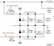
See the attached thumbnail ... I've marked the voltages in red.
A zener diode is one that has a specific breakdown voltage (14 in our case) when reverse biased. This leads to an avalance effect where when that voltage is reached it begins conducting current. This lets us use them to regulate voltages... put a resistor in series with a higher voltage and use the voltage across the diode. It's not complex.
In this circuit ...
the cathode of Z1 should read +14 volts
the anode of Z1 should read 0 (zero) volts
the cathode of Z2 should read 0 volts
the anode of Z2 should read -14 volts
Attachments
Last edited:
I sent my buddy a note that he can pick up his amp (and bring mine back) later today or whenever he'd like. We are both so grateful for all the help from the community! I am humbled by the generosity and time spent. I'm proud of the repair. Your help keeps a now perfectly functioning amp out of the landfill.
Wooo Hooo ... fixed!
However; sending it back so soon might have been a mistake. I would have wanted to hook it up, let it play music for a few hours and be sure it was all good first.
Wooo Hooo ... fixed!
However; sending it back so soon might have been a mistake. I would have wanted to hook it up, let it play music for a few hours and be sure it was all good first.
Maybe a bit of over-confidence on my part. The good news is that it's been playing music since that post non-stop. He won't be by until Saturday to pick it up, so I can power-cycle it a number of times and listen to it quite a bit more.
If for some reason it has a hiccup, then at least he's bringing my amp back 😀
Itsallinmyhead and Mr Blake especially - thanks for one heck of a fine thread!
Superb work and good for learning!
You're most welcome.
Nobody knows everything.
In my career I've learned one valuable skill ...
Never be afraid to switch hats from teacher to student.
Next time around it might be you guys helping me.
Last edited:
Maybe a bit of over-confidence on my part. The good news is that it's been playing music since that post non-stop. He won't be by until Saturday to pick it up, so I can power-cycle it a number of times and listen to it quite a bit more.
If for some reason it has a hiccup, then at least he's bringing my amp back 😀
There is one more test to try ... one most people never try... Turn the volume down... right down so that you have to put your ear up to the speaker to hear the music and be sure it's clean and clear. If there was any damage to the opamps or power amps, that should reveal it.
But if it makes it through the night, everything is alright...
Itsallinmyhead and Mr Blake especially - thanks for one heck of a fine thread!
Superb work and good for learning!
agree - great thread, great systematic checking of components with a thorough explanation why measurements were good or bad.
Learned a lot, bookmarked and will reference in the future.
That's very kind of you both. I'm more than thrilled that I asked for help. This has been a great experience made all the better if it helps someone else too.
There is one more test to try ... one most people never try... Turn the volume down... right down so that you have to put your ear up to the speaker to hear the music and be sure it's clean and clear. If there was any damage to the opamps or power amps, that should reveal it.
But if it makes it through the night, everything is alright...
Everything is groovy. My test speakers are not the most sensitive, but with my ear right up against the grills and the music playing softly enough to hear, there is no hiss, hum, or anything that makes me think something is amiss.
Going back to its rightful owner tomorrow, and I get my SissySIT, pre-amp and other loaned gear back.
On to another project. This has been a great deal of fun! Huge thanks to you.

Everything is groovy. My test speakers are not the most sensitive, but with my ear right up against the grills and the music playing softly enough to hear, there is no hiss, hum, or anything that makes me think something is amiss.
Many class AB amps have more distortion at low volumes because of a little phenomenon called a "Crossover Notch", a small point in time when both positive and negative halves of the amplifier are almost off. Because this is a small signal thing, turning down the volume most often reveals it.
But if it's nice and clear, all is good.
Going back to its rightful owner tomorrow, and I get my SissySIT, pre-amp and other loaned gear back.
On to another project. This has been a great deal of fun! Huge thanks to you.
Yeah, it was fun. My first remote control repair... 😀
Hello friends, this is my first post here.
I know the thread is a bit old, but I'll appreciate it if someone can help me bring my old RA150 back to life.
So far I couldn't find the solution, although some threads on this forum really helped.
English is not my native language, so excuse me for any grammar and language mistakes.
First, here is some background.
I bought my amplifier as a brand new unit, about 20 years ago (I can't remember the exact time). I sued it many years without problems
Also, I have masters and bachelor degree in electronics (graduated technical university in 2002) and I have some good experience with analog audio and television electronics. However, for the last 18 years I was working mostly as a soundengineer and OBvan engineer in local television channel, so most of the time I didn't have to repair electronic devices, except some basic repairs. Due to my other work obligations, I probably lost some of my experience and knowledge in electronics.
Here is the story of my amp and its repairs.
- I used it for many years in good environment and without overloading it. I didn't do any repairs and I didn't have any problems.
- Few years ago there was a problem - the sound of one or both speakers was cutting all of a sudden or not coming at all, when powering the amp. I checked (and this forum also helped) and I found that the original protection relay was faulty. I replaced it and used the amp without any problems for 2 more years.
- At some point the sound of both speakers started to cut for second and then coming back. It was accompanied by a click (like you connect a battery or other DC source to the speaker). The relay was also clicking, meaning that there is something wrong and the protection chain is activated. It was happening very rarely and I was too busy, so I didn't do anything to check what's wrong.
- At some point the protection chain started to activate too often (meaning the sound was cutting too often) and using the amp became annoying. I checked some useful information (this forum also helped) and opened the amp. There were some burned resistors on the power supply board - I replaced them. I also replaced the powerful resistors in the both amp boards. They weren't burned, but I did it just in case. Also, I noticed leaking from some capacitors. I replaced all capacitors on the power supply board (including those on the protection chain). Without connecting the cables for the other boards, I powered the amp and checked all voltages - all seemed fine, so I connected all the cables. The amp was working fine for a while.
- The protection chain started activating again. I tried disconnecting different cables and found out the left channel was working fine, when the right channel board is disconnected. And when I connect the right channel board (with the left one disconnected) the protection is activated immediately when powering the amp. At this point I was pissed of and put aside the amp for two years.
- Recently I decided to play with the amp again and try to revive it. Here are the steps I did:
1. I replaced all electrolytic capacitors on all boards, following the advise of a friend (very good engineer).
2. I tried to connect and disconnect different sets of cables to see what happens. According to the schematic, connectors J5-A and J6-A are connected to the right channel amp board. J5-A is +/- 40 V, ground and output. J6-A is the other connector with more tiny cables (+/- 15 V, TH2, protection signal and mono switch). When both J5-A and J6-A are disconnected, the protection isn't activated and the left channel works fine. When one of them is connected, the protection isn't activated and left channel works fine. When both J5-A and J6-A are connected, the protection is activated second after powering the amp and I can measure DC voltage about 4 volts on the output of the right channel.
3. I measured different voltages around the transistors on both power amps and both driver boards. There were huge differences on many points, but at this time I wasn't able to figure out where is the problem.
4. I desoldered both the driver boards (mounted on the power amp boards) and swapped them. According to the schematic and visual check, I think both driver boards are the same. When swapping them, the left channel kept working and the right one not. So it looks like there is no problem at the driver board, but at the power amp board.
5. At this point I disconnected all transistors on the right channel power amp board and measured them. They are all OK. I soldered them back.
6. With all transistors ok and all electrolytic capacitors replaced, I decided to do a visual check on the power amp board for any visible damages. I saw two corroded and damaged tracks (Is that the english word? I forgot...I speak about the "cables" printed on the circuit boards). I checked few times using magnifier. Then I checked with my multimeter tool. Yes, those two tracks were definitely damaged and there was no connection. One of them was providing +40 volts to the driver board and the other one was the protection signal.
7. I solved this problem and connected everything back to its place.
8. I checked the big transistors on the power amps, mounted on radiator. They are mounted with insulators. Before mounting I replaced the insulators with new ones. Needless to say - all parts I used for replacing are good and expensive ones...and much better than the ones they used in the factory. For example the original capacitors in my amp were cheap ones. I used ones with low leakage and extended working temperature. So, I checked the transistors right after mounting the boards for any possible short circuit with the radiator surface. I did good job.
9. The amplifier powered normally, then there was click when the relay was activated, but the protection wasn't activated after that. THERE! problem solved. By this time I was working with my speakers disconnected. I measured the voltage at the speaker terminals - no problems. So I connected the speakers. Everything looked fine so far, so I connected signal on the input...nothing. Both channels were not working. I disconnected the cables for the volume knobs and touched the "input" connector of the driver board. There was hum. I also connected audio signal there and I could hear it. But it was not loud.
10. It looked like the first stages of the preamp were not working. When checking voltages, I saw that the +/- 15 volts power is missing. This voltage was present when I started working, but now it was missing...no idea why. It is used for the integrated circuits. There is integrated circuit in the preamp of every channel and there is also one in the feedback circuit of every channel. These IC were not receiving power.
11. I checked the power supply and there was no +/- 15 volts. Both zener diodes Z1 and Z2 were damaged...you will excuse me - there are technical words I forgot how to translate on english, so I will explain the damage like this. I desolder both diodes. I measure them using my multimeter on diode mode. I checked the diodes connecting them both ways. One of them shows zero impedance in both directions. The other one shows nothing in both directions. So they were damaged. I'm really careful when connecting cables and soldering, I also check few times and I never do it with the power on. So I don't know why the zener diodes were damaged. Anyway, I bought few new ones.
12. After replacing the zener diodes and with the amp boards cables disconnected, I checked the voltages. I had +/- 15 volts. Then I connected all the cables and powered the amp again. The protection was immediately activated and there was some weird smell, before turning of the power. One of the zener diodes (the one on the -15 volts) was damaged immediately.
13. It is clear there is some problem, that appears only when I connect all the cables. It's like some sort of short circuit, but I have no idea why and where. Could it be the driver boards that I Swapped? But according to the schematic, both are the same and their connectors are also the same and positioned in the same way. The only difference between both channels is with the stereo/mono switch (and some parts connected to it), but these parts are on the power amp board, not on the driver board.
14. At this point I decided to do some experiment. It was probably wrong, but with no idea and being pissed of, I decided to do it anyway. Without replacing the zener diodes I had only +15 volts. The -15 volts was actually 0 (measured to the ground). So I don't think this could damage the integrated circuit. Both J5-A and J5-B were connected. They provide +/- 40 volts, ground and connect the channel output to the power supply board (the protection and relay chain). Then I tried connecting the other cable sets from the amp boards - J6-A and J6-B. When connecting one of them I still had +15 volts power. When connecting them both I could hear louder buzz from the mains transformer and the powerful resistors at the +/-15 volts chain got hot. Also the +15 volts power became +13 volts. It looks like connecting both J6-A and J6-B makes some sort of short circuit. But I have no idea why.
15. Next thing I did was to replace the damaged zener diode. Good thing I bought plenty of spare parts. Just in case I also replaced R401 and R402 - the powerful resistors at the +/- 15 volts chain. I measured the voltages (with J6-A and J6-B disconnected). I had +/- 15 volts. I believe connecting both J6-A and J6-B will lead to short circuit again and will damage some of the zener diodes. But it was worth trying connecting them separately. No problem. With one of them connected I had +/- 15 volts power and there is no heat.
16. Next thing I did was connect the speakers again. With J6-B disconnected and J6-A connected (it's the one of the right channel) the right channel is back online...but along with the music there is some weird noise (I can't describe it).
16. Then I did the oposite thing. J6-A is disconnected and J6-B is connected. When powering the amp the protection is activated soon after that, but before activating I can hear for a while that the left channel is also working. Also with that weird noise.
17. I'm out of ideas. Could it be swapping the driver boards was wrong? I checked the big transistors for possible short circuit again. No problems. What else...maybe some IC are damaged? Maybe I can swap the driver boards again and see what happens?
I'm sorry for the long post. Any advises and opinions will be appreciated.
I did some mistakes on my previous post. I'm sorry, I had to check carefully, before posting (where did I put my glasses 😉 ). Now I checked again.
18. There are two lines 16 on my previous post. But on both of them I have only noise. No music. But I can hear the noise only when I put the volume pot up, so the noise definitely comes from the preamp (based on one IC). Maybe the IC is damaged after all?
19. The cable connectors of the left channel board are not J5-B and J6-B. They are J3-A and J4-A. I know all the cables and where do they go, I just read them wrong from the schematic, when writing my previous post.
20. Another mistake I did - there is difference between both driver boards. R69 and C21 are mounted on the right one. Now they are on the left one. These elements are connected to the mono switch. I'm reading the circuit now and trying to figure out what these elements do and if they could possibly be the reason for my problem.
Some additional things I just did.
21. According to the schematic, J4-A and J6-A are not much different. Pin1 and pin2 of both are connected together and are also connected with the protection circuit. Pin 3 and pin 4 of both provide power +/- 15V. Pin6 of both are connected together and go to connector J8-A (somewhere in the LED board). Pin 5 has something to do with the mono switch. Pin 5 of both connectors are connected to each other and nowhere else. So...I don't see any reason for the short circuit (described above in my previous post).
22. The only idea that comes to my mind is that some IC are damaged and connecting both amp channels to the +/-15 volts supply overloads it and leads to damaging the zener diodes.
23. Another idea (is it stupid?) is to disconnect the feedback line going from the output of each power amp to the DC feedback circuit based on IC BA4560. If that IC is damaged for some reason, it could give (I haven't measure it) wrong voltage to the base connectors of Q5 and Q8 at the driver. And the output of this feedback circuit is also connected to the mono switch (through 10k resistor).
24. Where is the problem actually? Is it the preamp or the feedback circuit. Or both? Ok, I tried sending audio signal to the point after the volume pot (of the right channel). Thus I ignore the preamp, but the feedback circuit of the right channel still works. And the music is on, although not so loud without the preamp. I do the same without the feedback circuit (disconnecting J6-A stops the +/-15V power for the IC in the feedback circuit. I can still hear the music the same way.
Then I do the same with the left channel (all right channel cables are disconnected). With the feedback circuit on (J4-A connected and providing +/- 15 volts) the protection activates soon after powering the amp. But I can hear the music for a while (remember, the preamp stage is disconnected and the input signal goes after the volume pot). Without the feedback circuit, the left channel also works.
25. Writing all these stuff and following my train of thoughts I think I finally began to understand how the bridge mode of my amp works. Please tell me if I'm right or wrong, but maybe the mono switch (and the elements connected to it) actually change the current at the output of the feedback chain. And set the power amp on different mode. So after all maybe I have to swap the driver boards back to their original places. However. I never used my amp in mono/bridged mode and I don't plan to do it. And of course I still have no answer why the preamp stages don't work...
If anyone is interested in my problem, I solved it. It's the integral circuits in both the amp board and the driver board. Due to a failure I had earlier with the zener diodes (the ones that provide +/- 15v), one of the IC voltages was more than 15, so it destroyed 3 (out of 4) IC - the ones in both preamps and the one on the driver board of the right channel. They ones used in my amp are designed to work with no more than +/-15 volts. And since the power is +/- 15 volts, I thunk it is better to use IC with bigger headroom for power voltage, like +/- 20 volts. Unfortunately I had problem finding some good replacements right now. Some shops are closed due to the pandemic, some other shops usually deliver from abroard, but can't do it right now. Still, I installed IC DIP8 socket, instead of soldering the IC on the board, so later I may find other IC and replace them easily.
The original IC probably failed when I first had problems with the protection constantly activating few years ago. One possible reason is the corroded tracks on the right driver board, I mentioned earlier. With some of them damaged, the driver was not receiving proper power voltage, there was DC 4 volts on the output, but this voltage was also going on the input of the feedback chain. Theoretically it could destroy the IC in that chain. And with the IC destroyed, it could also lead to short circuit on the 15 volts power. Not sure if what I say is rubbish and no idea if this is what happened really, but I have no better idea at the moment. Maybe there were few different problems that (combined together) caused my problems. Anyway, the problem appeared to be very simple. Of course, after repairing and assembling everything, I will use the amp with cheap speakers for a while. Just in case. For now the voltages look ok.
And while no one answered my questions, I read about other problems here, and also tried to write about my problem, so it helped me in a way to look at my problem from different angles. So, thanks!
Important life lesson, folks!!!
Don't work when too tired ans short-sighted. Unless you want to fry some power transistors. Yes, I did. And yes, I sad fry.
After some successfull tests of the amp and after really long and hard day, I could really use some sleep and assemble the whole thing tomorrow. It takes some time and patience. But no, I had to finish it tonight (01:40), although, I'm not going to play music now. Well...long day and not seeing properly led to connecting one of the connectors wrong. The one that provides +/- 40 v to the right power amp. After power on I heard sound like frying something. I turned it off immediately, but two of the power transistors were really hot and I didn't need to test them (although I did) to know they are destroyed. Yep...few days work gone. Now I need to find new ones. I just hope I didn't burn some of the small transistors. Might check them tomorrow. Time to sleep.
- Home
- Amplifiers
- Solid State
- Repair of Alesis RA150