Ok it's been half an hour...
Where's it at?
If it's still in protection, you can try the shorting test on pins 1, 2 and 3 again ... one at a time.
See if one of them turns it on.
Where's it at?
If it's still in protection, you can try the shorting test on pins 1, 2 and 3 again ... one at a time.
See if one of them turns it on.
LEDs still just a glowin'
Pin 1 - about a 1/2 second delay and it shuts off the LEDs. No "Click"
Pin 2 - LEDs stay lit. No "Click"
Pin 3 - LEDs stay lit. No "Click"
Pin 1 - about a 1/2 second delay and it shuts off the LEDs. No "Click"
Pin 2 - LEDs stay lit. No "Click"
Pin 3 - LEDs stay lit. No "Click"
Last edited:
LEDs still just a glowin'
Try the shorting test like before.
LEDs still just a glowin'
Pin 1 - about a 1/2 second delay and it shuts off the LEDs. No "Click"
Pin 2 - LEDs stay lit. No "Click"
Pin 3 - LEDs stay lit. No "Click"
So we suspect pin 1 ... the overcurrent detector.
But no relay ... ???
You've got to get that relay working... Shut everything off, unplug the amp... wait a few minutes for everything to discharge ... With your ohms scale take a reading across D403 ... the diode will interfere one way, giving you a low reading... the other way you should be able to see the relay coil... at some large portion of it's DC resistance.
I seriously don't get why that relay is not working...
Noted. You and I are on the same page. I just pulled up the spec sheet for the relay (again) to try and make heads or tails of it just to try and absolutely and without question ensure I have a proper relay.
Before powering down, I also (just for my own peace of mind to ensure I wasn't missing a click of the relay audibly).. I did the quick and dirty check bypassing the protection, and ensured music. Then, I hooked the speaker to the terminals, and shorted pin 1. LED extinguished, but no music. No relay "click".
OK
D403 - 336.3 Red to Cathode / Black to Anode
D403 - 335.6 Black to Cathode / Red to Anode
What (at least I think) is odd - is that there is no low reading at all. Both ways very close to 336 ohms.
Bad D403?
Noted. You and I are on the same page. I just pulled up the spec sheet for the relay (again) to try and make heads or tails of it just to try and absolutely and without question ensure I have a proper relay.
Before powering down, I also (just for my own peace of mind to ensure I wasn't missing a click of the relay audibly).. I did the quick and dirty check bypassing the protection, and ensured music. Then, I hooked the speaker to the terminals, and shorted pin 1. LED extinguished, but no music. No relay "click".
OK
D403 - 336.3 Red to Cathode / Black to Anode
D403 - 335.6 Black to Cathode / Red to Anode
What (at least I think) is odd - is that there is no low reading at all. Both ways very close to 336 ohms.
Bad D403?
Very unlikely ... and it wouldn't cause it to look Open.
Do you still have the original relay?
If so... put it back in and see if it works.
If not ... Take that one out. Sand down the pins on that relay, flux them and tin them before putting them back in the board.
Last edited:
Alrighty - Out with the new; in with the old. Just from moving the board around on the standoffs, it's getting a few scrapes, but we don't have continuity anywhere we shouldn't.
I took out the relay - checked with 9V - it's OK.
Put in the original relay.
Fired it back up. Same stuff. Protection LEDs.
Tried shorting pin 1 - LED goes out. No satisfying "click" to accompany it. I checked the relay with a 9V again prior just to be sure. The resistance was 285ohms on the coil prior to putting it in.
Even though I'm not completely sure re: the purpose of the measurement. I did D403 again.
Black on Cathode / Red on Anode - 7.34kOhms
Red on Cathode / Black on Anode - 273.5Ohms
The odd part... maybe I wasn't making perfect contact, but the 2nd measurement, 273, started in the 10mOhm range. Note, I did this fairly quickly after powering down.
Pics are worth 1000 words. Maybe there's something physical I haven't caught.
Removal Top Side

Removal Bottom Side

Relay layout from side of original relay

Back in Top

Back in Bottom

I took out the relay - checked with 9V - it's OK.
Put in the original relay.
Fired it back up. Same stuff. Protection LEDs.
Tried shorting pin 1 - LED goes out. No satisfying "click" to accompany it. I checked the relay with a 9V again prior just to be sure. The resistance was 285ohms on the coil prior to putting it in.
Even though I'm not completely sure re: the purpose of the measurement. I did D403 again.
Black on Cathode / Red on Anode - 7.34kOhms
Red on Cathode / Black on Anode - 273.5Ohms
The odd part... maybe I wasn't making perfect contact, but the 2nd measurement, 273, started in the 10mOhm range. Note, I did this fairly quickly after powering down.
Pics are worth 1000 words. Maybe there's something physical I haven't caught.
Removal Top Side
Removal Bottom Side
Relay layout from side of original relay
Back in Top
Back in Bottom
It appears to be a two sided metal board. Maybe the through metal from top to bottom has been eroded by the removal & replacement of the relay.
Check continuity from U1 pin 6 (really R23 & R21 common point) to either top or bottom of the relay pin hole (coil) that goes to the not-line of D401. Note if it is top or bottom. Check continuity of line side of D401 to other relay coil pin. Also check that point to R417. Note if either is top or bottom. If either continuity goes to the TOP of the circuit board, check from top to bottom on both relay coil pins. If no continuity top to bottom you may have to add some.
Getting solder to flow from top to bottom is easy in the factory, doesn't always work when I do it. Did a jumper on a PV8 mixer last month. Ran a 28 ga wire from the component lead on top over to the next part lead on top, bypassing the broken top land entirely. Via through metal pulled off with the old pot I removed.
Last edited:
@indianajo - I think it's a single sided / single layer board. No through holes, and no traces or pads on the top side of the board anywhere. What leads you to believe it's a double-sided board?
Most of what you're saying is a bit over my head re: through line etc. I'll hold off, but thanks for the help.
Most of what you're saying is a bit over my head re: through line etc. I'll hold off, but thanks for the help.
All that green traces on top with black lines around it. Looks like the top side of the CRT monitor I'm working on. They leave the coating off the metal on the bottom where the solder is supposed to stick. Not on the top. The black lines on the top do NOT appear to echo the ones on the bottom.
Anyway, trace continuity from the part leads to the pads on the relay while relay is out. There could be a fracture somewhere. Check every connection, draw on the schematic with a yellow highlighter when okay so ensure you don't miss any path.
While relay is out recheck D401 that is .400 to .700 mv forwards, open backwards. Check from the pads.
Last edited:
D403 - 336.3 Red to Cathode / Black to Anode
D403 - 335.6 Black to Cathode / Red to Anode
What (at least I think) is odd - is that there is no low reading at all. Both ways very close to 336 ohms.
Bad D403?
D403 is in parallel to the relay coil. The 336 ohms you are seeing here is the relay coil.
Ah - gotcha. Thanks for the explanation. Per previous post, the relay is already back in, but I do like the idea of checking for proper continuity on the board.
Calling it an evening. I'll get back at it in the morning.
Thanks again.
Calling it an evening. I'll get back at it in the morning.
Thanks again.
All that green traces on top with black lines around it. Looks like the top side of the CRT monitor I'm working on.
It looks like the top side is painted green with the trace outlines of the bottom side of the board painted on top. Single sided board. The jumper wires on the board point to single sided as well.
Last edited:
Alrighty - Out with the new; in with the old. Just from moving the board around on the standoffs, it's getting a few scrapes, but we don't have continuity anywhere we shouldn't.
I just spotted this ... Want to see an example of bad design... here it is...
Take a look at the relay coil contacts, indicated by the arrows. The foil for the top one wraps right around a mounting point for the board. Neither side of that coil is grounded. Judging by the scratches it sits on a metal standoff ... a dead short, waiting to happen.
Don't know what the trace on the opposite side of the hole is, but it's at risk too!
I strongly recommend either adding a fibre washer to that mounting point or replacing the stand-off with a plastic one. (maybe others too...)
Although the enlarged section of the photo is not very clear, I would recommend reflowing those two solder points, with a fair bit more heat applied and more solder. They don't look like good joints to me.
Attachments
Last edited:
It looks like the top side is painted green with the trace outlines of the bottom side of the board painted on top. Single sided board. The jumper wires on the board point to single sided as well.
I agree ... it looks like single sided board. I see no evidence of plate through or vias anywhere.
OK - I admit that I "went rogue". I'm an Occam's razor kinda guy, so I was looking for a simple solution. Everyone has been exceptionally helpful. Douglas, whatever your favorite beverage of choice might be, if I ever run into you (or can send something to you), it's yours.
Anyway... One thing that (I think) I know how to do is check for proper continuity, check for dead shorts etc.
So here is what I have done so far. No flogging for effort (even if it's misguided).
We want the relay to engage. So, after fiddling (yes, again) and wiggling things before removing the board I found an intermittent connection at J2 due to the pins in the plastic connector on the transformer side. I don't think this is related to the core issue at hand, but I can't disregard it related to the intermittent appearance of the LEDs. I did my best to snug all the wires and their connections tightly back into the housing. The board-side connection and its pins seems solid. It was the side running to the transformer. The symptom appeared when I wanted to test the theory around the dead short of the mounting hole near the relay. I simply took all the screws out and lifted the board. The protection lights went away, then flickered. I traced it to J2. Wiggling J2 caused the LEDs to flicker on and off. No dead short at that mounting hole, but I'll also try the nylon washer when I remount it.
Onto the "rogue" part. I took my trusty 9 volt and put it across the solder joints on the relay coil. "Click". To me, that meant that we had a solid connection from solder to pads, to pins, to board, to other side. But, just for good measure, I removed all the solder again, cleaned the pads, and re-soldered the joints. 9V and lovely "click". Now, in fairness, I recognize that this isn't under current, but it was the best I could think to do to test it in situ.
So, I started doing what I always do... tracing the circuit. I ran the 9V leads to all adjoining points on the same (not sure what the correct term is) copper planes. Better than the beep from a DMM for continuity is the solid "click" from a relay snapping.
I did a number of checks from the direct relay points, then I moved to the pads on D403. Here's something maybe interesting.
See schematic and picture below.


These two points do not have continuity. I think they're supposed to. I originally thought it may be due to a bad solder joint on D403, so I removed the part with the intention of cleaning the legs etc. and fully cleaning the joint. Even after removing the part, there is still no continuity between these pads. I even removed the solder again from that side of the relay to check "pad to pad".
Am I onto something, or am I fundamentally mistaken that there should be continuity here? It makes sense on the board, and it shows a direct connection in the schematic.
Is it unwise to run a small wire between these points and test? For the life of me, I can't figure out why there's no continuity. The relay pad has continuity to the "scratch", and so does the pad for D403, but no continuity between them.
I'm currently going with the simplest explanation that (the big ol' scratch was there before I got to work on the board - I own the scratches around the mounting hole) either I or someone previously damaged the board in this area. Crazy? Worth pursuing?
Anyway... One thing that (I think) I know how to do is check for proper continuity, check for dead shorts etc.
So here is what I have done so far. No flogging for effort (even if it's misguided).
We want the relay to engage. So, after fiddling (yes, again) and wiggling things before removing the board I found an intermittent connection at J2 due to the pins in the plastic connector on the transformer side. I don't think this is related to the core issue at hand, but I can't disregard it related to the intermittent appearance of the LEDs. I did my best to snug all the wires and their connections tightly back into the housing. The board-side connection and its pins seems solid. It was the side running to the transformer. The symptom appeared when I wanted to test the theory around the dead short of the mounting hole near the relay. I simply took all the screws out and lifted the board. The protection lights went away, then flickered. I traced it to J2. Wiggling J2 caused the LEDs to flicker on and off. No dead short at that mounting hole, but I'll also try the nylon washer when I remount it.
Onto the "rogue" part. I took my trusty 9 volt and put it across the solder joints on the relay coil. "Click". To me, that meant that we had a solid connection from solder to pads, to pins, to board, to other side. But, just for good measure, I removed all the solder again, cleaned the pads, and re-soldered the joints. 9V and lovely "click". Now, in fairness, I recognize that this isn't under current, but it was the best I could think to do to test it in situ.
So, I started doing what I always do... tracing the circuit. I ran the 9V leads to all adjoining points on the same (not sure what the correct term is) copper planes. Better than the beep from a DMM for continuity is the solid "click" from a relay snapping.
I did a number of checks from the direct relay points, then I moved to the pads on D403. Here's something maybe interesting.
See schematic and picture below.
These two points do not have continuity. I think they're supposed to. I originally thought it may be due to a bad solder joint on D403, so I removed the part with the intention of cleaning the legs etc. and fully cleaning the joint. Even after removing the part, there is still no continuity between these pads. I even removed the solder again from that side of the relay to check "pad to pad".
Am I onto something, or am I fundamentally mistaken that there should be continuity here? It makes sense on the board, and it shows a direct connection in the schematic.
Is it unwise to run a small wire between these points and test? For the life of me, I can't figure out why there's no continuity. The relay pad has continuity to the "scratch", and so does the pad for D403, but no continuity between them.
I'm currently going with the simplest explanation that (the big ol' scratch was there before I got to work on the board - I own the scratches around the mounting hole) either I or someone previously damaged the board in this area. Crazy? Worth pursuing?
Last edited:
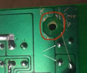
It's hard to see the "scratch" in the picture but what you are describing sounds more like a cracked trace. If that's the case you can either remove the solder mask and solder a wire across the crack or go point to point between the relay pad and the diode pad.
Last edited:
It's hard to see the "scratch" in the picture but what you are describing sounds more like a cracked trace. If that's the case you can either remove the solder mask and solder a wire across the crack or go point to point between the relay pad and the diode pad.
Thank you. Apologies. I didn't see that the previous picture was so out of focus. See below. I circled the "big" scratch that was there when I first removed the board. The other scratches around the standoff hole, I created with the multiple removals etc.
I'll run a small wire and see where that takes me.
Thanks!

The cracked trace will likely fix up the relay engagement problem. The odd behavior of the protection circuit itself is another issue. The intermittent connection of the supply transformer may be the root of the though.
- Home
- Amplifiers
- Solid State
- Repair of Alesis RA150