This has to be a bad connection...
First of all, the instant those lights go out the relay should pull in.
Second if probing it changed it's behaviour it is almost certain to be a bad connection.
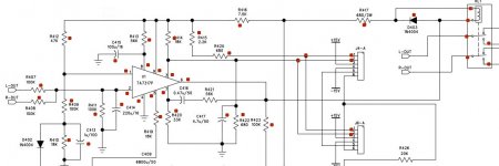
Now ... for each of the parts I marked with a red dot. You need to check the solder work, with a magnifying glass, and resolder any that look even remotely suspicious.
Realy cook them down... apply heat and stay on them for a few seconds each. If any of the boil or smoke, remove the old solder and resolder the connection.
When done, clean the board with alcohol to remove any trace of flux and look at them again...
We can't get a good diagnosis with bad connections... and, in fact the whole problem might well have been a bad connection from the beginning (eg R417)
Dang... this is frustrating...
First of all, the instant those lights go out the relay should pull in.
Second if probing it changed it's behaviour it is almost certain to be a bad connection.
Now ... for each of the parts I marked with a red dot. You need to check the solder work, with a magnifying glass, and resolder any that look even remotely suspicious.
Realy cook them down... apply heat and stay on them for a few seconds each. If any of the boil or smoke, remove the old solder and resolder the connection.
When done, clean the board with alcohol to remove any trace of flux and look at them again...
We can't get a good diagnosis with bad connections... and, in fact the whole problem might well have been a bad connection from the beginning (eg R417)
Dang... this is frustrating...
Attachments
No... that won't help.
Turn the amp off.
Wait 2 minutes or so. (pee break?)
Turn it on and see what it does.
Don't do anything... just sit there and watch it for a couple of minutes.
LEDs back on.
T=0
T=10 min
No changes. No clicks... Nada.
This has to be a bad connection...
First of all, the instant those lights go out the relay should pull in.
Second if probing it changed it's behaviour it is almost certain to be a bad connection.
Now ... for each of the parts I marked with a red dot. You need to check the solder work, with a magnifying glass, and resolder any that look even remotely suspicious.
Realy cook them down... apply heat and stay on them for a few seconds each. If any of the boil or smoke, remove the old solder and resolder the connection.
When done, clean the board with alcohol to remove any trace of flux and look at them again...
We can't get a good diagnosis with bad connections... and, in fact the whole problem might well have been a bad connection from the beginning (eg R417)
Dang... this is frustrating...
I agree. I'm just going crazy b/c I feel like this is a tremendous waste of both your talent and time. I'll go through the board with a fine-toothed comb.
I'll focus on the parts you've noted, but I'll literally go over the whole board with my loupe+readers to check for anything suspect. That and the continuity check is how I found the nerd between the two pins of J4-A.
With other things that I troubleshoot, irregular behavior almost always comes down to something physical that changes due to heat or other environmental conditions. Or.. just something physically loose that vibrates.
At this point, I think I would get that board completely out of the amplifier, flip it upside down, reheat every last solder point, add a bit of fresh solder and let it cook for a couple of seconds.
This should be a simple diagnosis... find which of the three protections is triggering the chip and fix it... but it's behaviour keeps changing. Until it is consistantly fixed or consistently bad, it's going to be almost impossible to diagnose... especially by remote control.
When you get it back together, let me know what it does...
While you were typing that, I had the board out.
I first cleaned the board.
Then, I examined it under the loupe with my readers. I didn't see anything of concern.
I went point by point from top to bottom of the board - applied a tad of flux, and reflowed each joint with a touch of new solder. Holding to ensure proper flow and contact.
Cleaned the board - ridiculously thoroughly - and reinstalled the board.
Popped the board back in.... Protection lights.
Re-checked per above.
Pin 1: (-)68mV
Pin 2: (-)1.2mV
Pin 3: 346mV
Re-ran the shorts to ground.
Pin 1 - Very slight delay to turn off. Immediately back on
Pin 2 - Protection LEDs stay on and remain on. No blinking.
Pin 3 - Protection LEDs stay on and remain on.
I can't be sure if I've affected a change with cleaning / touching things up and/or if the amp just has not warmed back up. I'm going to let it sit for an hour and see if the LEDs remain lit. If they are, then I'll re-run the pin checks to see if anything has changed.
Cheap parts, resistors & capacitors, sometimes have bad welds inside. Push all the components with the power on to see if it causes the relay to pick up or not, the protection led to go out momentarily. Use an insulator like a dried ball point pen or something. Also the thermal switch and anything on that circuit. Bad crimps in connectors can also occur. Push on the wires to the connectors.
This is one of the areas where an analog VOM or scope is better than a DVM. With the probe clipped to the dodgy voltage pins or a lead of some component connected to them, watch the voltage jump as you push things. A DVM averages over 2-4 seconds, a VOM pointer can respond as fast as 60 hz. Really; I plugged a cheap Micronata meter in the wall on 500 v dc and the pointer vibrated 170 to zero!
This is one of the areas where an analog VOM or scope is better than a DVM. With the probe clipped to the dodgy voltage pins or a lead of some component connected to them, watch the voltage jump as you push things. A DVM averages over 2-4 seconds, a VOM pointer can respond as fast as 60 hz. Really; I plugged a cheap Micronata meter in the wall on 500 v dc and the pointer vibrated 170 to zero!
Last edited:
@indianajo -
LOL! I JUST got done trying that while the amp was continuing to warm. Clearly I don't know a whole ton about circuits, but intuition tells me:
1) bad joint - hopefully took that out of my mind.
2) bad part (irregular / sketchy, but not completely toast). Thermals may affect it.
So, I took a chopstick and pushed, poked, prodded and otherwise messed about trying to get SOMETHING to note a change. Sadly, I didn't have something like a fixed probe point to watch for voltage fluctuations, but I was hoping upon hopes the relay would "click" as I poked something.
When I left the amp after literally poking it with a stick... Protection LEDs were lit.
One hour after firing it back up (post reflow and clean) - I went back to check on it.
Protection LEDs out.
No DC
R417 - 0V0 Across. 45V1 legs to GND
D403 Anode - 833mV
D403 Cathode - 44V1
Pin 1 - Junction of U1 and R409, R412: (-)247mV Still does not seem steady
Pin 2 - Junction of U1 and R407, R411 and positive side of C414: (-0.8mV)
Pin 3 - Junction of U1 and R414: 345mV
Pin 4 - Assume it's got solid continuity to GND
Pin 5 - Junction of U1 and R419: (-)0V73
Pin 6 - Junction of U1 and R423: 0V833
Pin 7 - Junction of U1 and R420: (-)0.08mV
Pin 8 - Junction of U1 and R413: 1V37 Still does not seem steady
Pin 9 - Junction of U1 and R413 (opposite side of R413 to Pin 8): 3V2
Pin 6 seems to swing a lot based on whether we have LEDs on or off....
I know the test is supposed to be done starting with LEDs on, but why not...
Short to GND
Pin 1 - LEDs stay off
Pin 2 - LEDs stay off
Pin 3 - LEDs stay off
This thing is possessed. Short of just swapping out all the passives... I have no clue whatsoever.
There are always the hair dryer to heat passives, and the circuit cooler can to freeze them. A plastic bag with ice piece in it may substitute for circuit cool spray. Make note of what part(s) you are directing heat/cool to when the voltage on 6 (output) changes. Change passives around there.
Can't use a soldering iron to head passive leads with power on because most of them have the tip safety grounded. If you have a bernzomatic butane gas one though - - - Also same trick, a battery powered soldering iron.
Can't use a soldering iron to head passive leads with power on because most of them have the tip safety grounded. If you have a bernzomatic butane gas one though - - - Also same trick, a battery powered soldering iron.
Last edited:
This thing is possessed. Short of just swapping out all the passives... I have no clue whatsoever.
Randomly changing parts is the desperate act of a failed technician.
It's not possessed ... it's broken. Our job is to figure out why and fix it. We do this by a combination of things... We follow the schematic to understand the circuitry, we take measurements to determine what state that circuitry is in... then, when we isolate a fault we do a repair. The task is straight forward and logical.
Right now we have an amplifier that does come out of protection. That it takes too long is irrelevant... it does try to work. The protection leds switch off but the relay is not pulling in... That is the immediate problem... why is that relay not pulling in?
Forget everything else, get focused on that one problem...
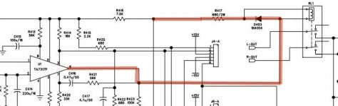
Lets follow the schematic... R417 is connected in series with the relay coil so we know that whatever current passes through one should be passing through the other. Now we can use Ohm's law to figure out what those voltages should be...
R417 is 680 ohms.
The relay measured at 368 ohms.
From message#55...
Ohms law says that we should be seeing...
680 ohms for R417 + 368 ohms for the coil ... so 45/ (680 + 368) == 45/1048 == ~43ma of current.
Thus R417 should have 680 X .043 == ~29.4 volts across it
So one leg should read the bulk supply and the other should read 45 - 29 == 16 volts.
thus D403 should read 16 volts on one leg and nearly 0 on the other.
D403 is not of concern, it is simply an easy way to access the relay coil from the top of the board.
Now... with the protection leds finally off ... we can measure the voltage to ground on both sides of D403 ... we should expect about 14 or 15 volts on the cathode and about 2 volts on the anode.
Per your last set of readings you had 45 volts on the anode and almost nothing on the cathode ... that is too high... Now the whole thing collapses into one simple question.... Why is it too high? ... for the moment that is what we care about.
Again look at the schematic... When you probe D403 you are, in effect, reading the voltage across the relay coil. The only reasons it is too high is that the relay coil is either not connected or burned out. Given that you took two relays out of there that both had good coils in them... I'm pulling toward "not connected" and since it's right on the board... that tells me "bad solder".
So that's where we are ... we have an amp that does come out of protection, albeit slowly but does not energize the relay. We need to fix that before we move on...
Remove the solder from the relay coil contacts... heat it up real good, add some new solder and cook it down real good after.
Now... put a piece of cardboard over the standoffs supporting that power supply board so there's no risk of shorts... fire the thing up, wait for the lights to go out and tell me what happens.
No readings, no probing things with sticks... just turn it on and observe it's behaviour...
Last edited:
There are always the hair dryer to heat passives, and the circuit cooler can to freeze them. A plastic bag with ice piece in it may substitute for circuit cool spray. Make note of what part(s) you are directing heat/cool to when the voltage on 6 (output) changes. Change passives around there.
Can't use a soldering iron to head passive leads with power on because most of them have the tip safety grounded. If you have a bernzomatic butane gas one though - - - Also same trick, a battery powered soldering iron.
First you have him poking the thing with a stick, next you want him to induce huge thermal stresses and then follow it up by soldering on a live circuit...
Really???
WTF is wrong with you???
@Douglas Blake - you have the patience of Job. I have no way to properly convey my appreciation.
Just so I'm sure. I need to wait for the protection LEDs to extinguish prior to doing the checks you've mentioned, correct? What is perplexing me (and having me jokingly call the amp "possessed" is that the LEDs come on when the amp is "cool" and then cut off after some period of time. My speculation is either parts finally getting the voltage they need (or reducing to a correct point) and/or heat stressing a part.
I love the methodical approach. It's how I conduct troubleshooting in my actual profession. I get frustrated with "knob turners" that don't find root cause before noodling with dials. I may have a bit more empathy toward them going forward 😀
I just measured Vgs and sorted 24 MOSFETs for a friend, so I'm feeling accomplished and in good spirits. Back to the amp I'll lovingly call... %$#$ 😀
I waited a bit too long to edit. I re-read post #110 and understand completely.
Should I leave in the 10k resistor or remove?
Should I leave in the 10k resistor or remove?
@Douglas Blake - you have the patience of Job. I have no way to properly convey my appreciation.
Trust me, I have limits too ...
Just so I'm sure. I need to wait for the protection LEDs to extinguish prior to doing the checks you've mentioned, correct?
No checks ... turn it on and wait for the protection leds to go off. At the same time as they go off you should hear the relay click in.
Power... protection... CLICK... music... Eureka!
What is perplexing me (and having me jokingly call the amp "possessed" is that the LEDs come on when the amp is "cool" and then cut off after some period of time. My speculation is either parts finally getting the voltage they need (or reducing to a correct point) and/or heat stressing a part.
When you first turn any electronic circuit on it is in a very unstable state. Capacitors aren't charged, outputs aren't biased, etc. Thus, it is normal and expected for the amp to power up in protection mode. It is also normal and expected that it will stay that way until it is safe to turn protection off. This is by design to protect the speakers from huge turn on thumps until the internals settle down.
If it did not come up in protection for at least a couple of seconds, we should be very worried.
I love the methodical approach. It's how I conduct troubleshooting in my actual profession. I get frustrated with "knob turners" that don't find root cause before noodling with dials. I may have a bit more empathy toward them going forward 😀
There are a lot of outright incompetent people in electronics. I've seen everything from people who pull out the books, check this, check that and then get lost when the step by step script fails them all the way to papered engineers I wouldn't hire to drive a train.
Of course there are good people too. Some of them are here, I recognize their names... but they are fewer and further between with each passing year.
We are moving into an age of incompetence. Technical skills are atrophying at a mind numbing rate. Where technicians used to do what we're doing and climb right into a circuit, now they can barely exchange circuit boards without an instruction manual.
From the mid-80s to the early 2000s I used to teach a course in introductory electronics for my employer. When we first started we were hiring kids out of high school and most of them already had the basics... They understood Voltage and Current, most knew Ohm's law and they all had some experience with basic hand tools. In the first 15 years I don't recall releasing more than a handful of trainees, virtually all went on to be apprenticed with a technician. Towards the end we were hiring from community college and I was dismissing half of my students in the first week. They knew nothing, I was starting with "This is a piece of wire". They were becoming unruly, uninterested, messing with their iPods.
One of these days, the lights will go off and nobody is going to be able to get them back on.
Last edited:
I waited a bit too long to edit. I re-read post #110 and understand completely.
Should I leave in the 10k resistor or remove?
I would leave it there ... it holds the protection lights on in case of another relay failure so it's a good indication that the relay has failed again.
Power ... protection ... lights out... no sound ... probably the relay.
OK - last question before moving things back. I've removed the solder from the relay pins. Re-checked resistance across the relay pins - 358 Ohms. Re-soldered.
Re: the cardboard. There is one standoff hole on the board that connects to ground via the standoff. Are we intentionally "bypassing" that ground with the cardboard between the board and the standoff or should I ensure a connection there? It shares the same pad with one leg of R424 one leg of Q402 etc.
I can easily just mount the board back to place unless it's intentionally part of the troubleshooting to remove this ground point.
Thank you!
OK - last question before moving things back. I've removed the solder from the relay pins. Re-checked resistance across the relay pins - 358 Ohms. Re-soldered.
Re: the cardboard. There is one standoff hole on the board that connects to ground via the standoff. Are we intentionally "bypassing" that ground with the cardboard between the board and the standoff or should I ensure a connection there? It shares the same pad with one leg of R424 one leg of Q402 etc.
I can easily just mount the board back to place unless it's intentionally part of the troubleshooting to remove this ground point.
Thank you!
I was just trying to save you the trouble of mounting and dismounting it all the time. It should work either way.
Oh - OK - thank you. I just wanted to be sure. I remounted it - may as well remove that variable.
Amp is fired back up with fresh and gorgeous solder on the relay pins.
Protection LEDs immediately light.
I will let it sit until the "lights go out". They will eventually based on previous behaviour.
Hopefully when they do, the relay will kick in when they go out. Must.... resist.... taking.... measurements...
Oh - OK - thank you. I just wanted to be sure. I remounted it - may as well remove that variable.
Amp is fired back up with fresh and gorgeous solder on the relay pins.
Protection LEDs immediately light.
I will let it sit until the "lights go out". They will eventually based on previous behaviour.
Hopefully when they do, the relay will kick in when they go out. Must.... resist.... taking.... measurements...
Yep... wait it out.
At this point you could probably put some music through it... at a low level, with a pair of old speakers. You would not be trapped there waiting, you could just listen for the music to start.
If the lights don't go out ... then we take some measurements.
- Home
- Amplifiers
- Solid State
- Repair of Alesis RA150