I will not lift R412. @Douglas Blake. Noted with thanks.
If not, I'll pop C415 back in and get to work.
Now that we know it's not a bad capacitor....
Let me first acknowledge that this is a very tedious process to do online. If we were shoulder to shoulder at a test bench, everything we've done so far would have taken us less than an hour, complete with the explanations. These are fairly rudimentary tests to determine what is holding that chip off from pulling in the relay and for the most part they are a matter of "touch here and check the meter"... which doesn't take very long at all.
Bypassing the amp's protection is an absolute last resort, to be taken only if there is a part we can't get.
Putting in a third party protection board is a very extensive modification that does not guarantee success. We can't trust that any more than we can trust what we have now.
Note that pin 1 gets it's voltage from the chain of R409 and D402 ... D402 connects to pin 1 of J2 which leads to the power transformer's secondary coils. The diode samples this AC voltage, rectifies it and charges c413 to roughly -40 volts. This charge is then divided by R409 and R412 to hopefully provide less than 0 volts at pin 1. Thus, if too high a load dragged the transformer secondary down by more than a volt or two the voltage at c413 would increase, driving pin 1 above threshold, triggering protection. Although it's a bit primitive, this forms a workable over-current detector.
So the next logical step is to reinstall C415 set the board back into the case, install any grounding bolts, set up with the clip lead on chassis ground as before and do a repeat set of readings. We need to confirm the readings are as before, before we go to the next step...
To help you along, I'm attaching a screen shot from a Marantz schematic with the voltages marked by the factory...
Attachments
Last edited:
I had SUCH high hopes.
Here's what I did and why.
I actually went ahead and took out U1. I thought, "what could it hurt"? More to come, but I think I successfully removed it. Checked all pads for continuity to their close partners on the board. No issues. However... I was tracing from one of the pins along and checking continuity along the circuit. As I was doing so, I saw what I thought was an iddy-biddy solder bridge or some flotsam between pins 1 and 2 of J4-A. There was continuity between the pins. I cleaned that out. No unexpected continuity.
I had such high hopes that may have been the issue. Replaced C415 and U1.
Powered back up - Protection again... 😡
So, back to basics since I clearly made (what may be) a meaningful change to the protection circuit by cleaning up that area.
No DC - Checked L1 and L2 to GND: <10mV
Voltage across R417: Crazy... moves back and forth from 400mV or so to 45V as I wiggle it.
Next step is to remove board once again... lift leg of R417 and see how it measures. If it measures properly (680 Ohms), I'll inspect traces/pads etc, and solder back in place, and re-measure voltages/check points from the beginning.
Off we go...
Well, R417 measured 666 Ohms.That could be telling... (j/k)
LOL ... sure could.
Powered back up - Protection again... 😡
Hmmm... not good. That solder bridge you found could have triggered protection... since it's on pin 3 of the chip.
Voltage across R417: Crazy... moves back and forth from 400mV or so to 45V as I wiggle it.
Yep, that's a bad solder joint for sure ... resolder both legs and cook it down a bit.
I'll inspect traces/pads etc, and solder back in place, and re-measure voltages/check points from the beginning.
Off we go...
Excellent.... For the next step I really need to see the voltages on that chip.
OK - Well, now I'm so confused that I'm not sure if it was two steps forward, and one back or just one back...
Here is where we are after checking and ensuring R417 was solidly connected in the circuit.
Protection lights are now OFF again. Still no blue power light.
Checks we have done in the past.
No DC at L1 and L2.
Voltage across R417 - Rock solid 0V0
Speaker Cheater test - A-OK Amps are still good.
Cathode (Stripe) side of D403: 44V7
Anode side of D403: 6.3mV
Edit - Corrected
If I interpreted this correctly from previous posts, that means the coil in the relay is not conducting... I think...
Pin 1 - Junction of U1 and R409, R412: (-)120mV This climbs consistently.
Pin 2 - Junction of U1 and R407, R411 and positive side of C414: (-0.08mV)
Pin 3 - Junction of U1 and R414: 347mV
Pin 4 - Assume it's got solid continuity to GND
Pin 5 - Junction of U1 and R419: (-)0V75
Pin 6 - Junction of U1 and R423: 6.4mV
Pin 7 - Junction of U1 and R420: (-)0.08mV
Pin 8 - Junction of U1 and R413: 615mV This one takes a while to get there. Unsteady. Continues climbing.
Pin 9 - Junction of U1 and R413 (opposite side of R413 to Pin 8): 3V2
So it's not showing protection any longer, which I suppose is good news b/c we have found nothing (other than maybe the flotsam between the pins) that would cause an "actual" fault to trigger the circuit. However, we still have no tunes w/o "cheating".
Last edited:
OK - Well, now I'm so confused that I'm not sure if it was two steps forward, and one back or just one back...
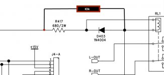
Alright ... lets get this set up so we can discern whether the amp is actually in protection or if the relay is simply not being pulled in...
Have you got a resistor in the 10k range with good leads?
Without doing anything else... Touch the leads as shown... the hot side of R417 to the anode of D403 .... do the protection lights come on?
Now with that resistor still in place, turn the amp off and back on... what do the protection lights do?
Now if this simple test works, you should go on the back of the board and perminently attach this resistor across the solder points as shown. This will let us see the protection light status even if the relay and R417 is completely fried.
This gives us much more information ...
Protection lights on, something is triggering protection.
Protection lights off, no sound ... the relay or R417
Protection lights off, music playing ... Eureka! It works.
Attachments
Last edited:
Alright ... lets get this set up so we can discern whether the amp is actually in protection or if the relay is simply not being pulled in...
Have you got a resistor in the 10k range with good leads?
Without doing anything else... Touch the leads as shown... the hot side of R417 to the anode of D403 .... do the protection lights come on?
Yes.
Now with that resistor still in place, turn the amp off and back on... what do the protection lights do?
They come one / stay on.
Now if this simple test works, you should go on the back of the board and perminently attach this resistor across the solder points as shown. This will let us see the protection light status even if the relay does not pull in.
I'll try to get this going, but will likely have to pause for the evening. It's beginning to be 'Tis the Season. 😀
I truly can't thank you enough. I have not gone back to explore the schematic to understand this "magic" re: the new resistor, but I will.
I'll post back either right after finishing (likely in the morning). I've already heard one "Are you almost ready?". 😀
Yes.
They come one / stay on.
Ok, that's good.
There is a very real chance that either the relay or R417 will burn out. Or with the amount of messing around, bad solder joints are a real possibility.
Now... when you are installing that resistor on the back of the board. Also remove R417 completely, both legs... Clean the legs with a bit of sandpaper and tin them. Clean the circuit board pads.
Test the resistor again, this time applying a gentle bit of pressure to twist or distort the resistor... see if it loses continuity under moderate stress... if it does you're going to have to replace it. If you have to replace it I would suggest using 720 ohms as this will reduce the stress on the relay coil somewhat.
Reinstall R417 and connect the new 10k across the pads as shown. Once again using extra solder and really cook them down.
Get the whole thing together and we'll continue.
Oh - Rats....
I already soldered the 10k resistor in and put the board back in.
Good news is that when I did R417 earlier, I did exactly what you described... The only thing I did not do is torque it around. I scraped it, ran some rosin across the legs and heated to clean / deoxidize, cleaned, and tinned. I tried to find a similar value in my stash. I don't have any 2-3W resistors in that range. I see where you're going though. That resistor has physically seen better days - no doubt. I'll wiggle and jiggle it, but it's holding rock steady at 44V66 on each side to ground.
All back together with the 10k installed. Fired it back up and protection lights are on.
Pausing for the day.
Once again.... truly appreciated. I also need to go back and digest post #81 with the Marantz schematic.
Have a wonderful Friday evening.
I'll get back at it in the morning.
I'll get back at it in the morning.
Okey dokey .... When you start up again, here's what we do next...
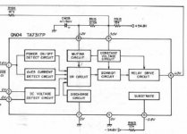
If you study the schematic for pins 1, 2 and 3 of the TA7317 you will discover these are all connected out to the rest of the amp by fairly high resistance values. This is good because it lets us force certain conditions without damaging anything or massively disassembling the board.
So, get the board together, remount it, put in the grounding screws and fire it up... we're going to let it sit while you go get your morning coffee so it's nicely settled in and all warmed up.
There are three things that can cause protection here... Over current, DC offsets and thermal. So we need to test each of these separately to see which one is triggering protection.
The setup...
You will need a clip lead on ground with a pin or stiff piece of wire at the other end, to act as a probe. What we are going to do is force the protection inputs to ground one at a time to see if we can get the thing working. The TA7317 does not latch so once the fault is removed it should cycle automatically to active mode.
Note: If this doesn't cause a nervous sweat, I don't know what will. Keep in mind that you are inside a live amplifier with a piece of wire that is a dead short to ground... It's not a good time to be clumsy.
1) Over current
The over current sensor links to pin 1 through R412 and R409. Test the voltage here first. Now with your grounding probe touch the leg of R412/pin1. Hold for a good 10 seconds to see if the protect lights go out and/or the relay pulls in. If it does we know this was what was triggering protection and we can concentrate on this circuit.
2) DC offset.
This is on pin 2 of the chip. Take a voltage reading from R411/Pin1 first then touch it with your grounding probe, holding it for at least 10 seconds. I doubt this is what's triggering it, but if it is the protection lights should go out.
3) Overheating
I think we both suspect this one. I really don't like the voltage reading on Pin3. Take a reading from R422/pin3 first. Then put your grounding probe on it for a few seconds and wait for the lights to go out.
Once we know which of the three is causing protection, we can concentrate on getting those parts of the circuit sorted out.
There is one other possibility ... The output on pin 6 of the chip is blown and can't pull in the relay even if it should. But testing that means replacing the chip... so we go by process of elimination eliminating triggers first. When there's no other explanation, then it's time to change the chip.
Last edited:
I am properly caffeinated and ready to go. I saw the notes last night, and I wanted to see how values changed (and if this thing would ever get "stable"). So I left it on overnight and did the following checks again. Red notes what I think may be a meaningful change.
No DC at L1 and L2.
Voltage across R417 - Rock solid 0V0
Cathode (Stripe) side of D403: 44V7
Anode side of D403: 40V77
Pin 1 - Junction of U1 and R409, R412: (-)147mV Still does not seem steady
Pin 2 - Junction of U1 and R407, R411 and positive side of C414: (-1.7mV)
Pin 3 - Junction of U1 and R414: 345mV
Pin 4 - Assume it's got solid continuity to GND
Pin 5 - Junction of U1 and R419: (-)0V71
Pin 6 - Junction of U1 and R423: 40V7
Pin 7 - Junction of U1 and R420: (-)0.08mV
Pin 8 - Junction of U1 and R413: 1V3 Still does not seem steady
Pin 9 - Junction of U1 and R413 (opposite side of R413 to Pin 8): 3V2
Now on to the new set of measurements.
Drum roll, please.
I rocked at Operation as a kid.
(-) 218mV. Climbed from even a moment ago. Swapped DMMs to confirm and double check these "wandering" measurements. As I was measuring R412 and R409, the protection LEDs went out. 😕 This is prior to running the shorting check.
I just have to believe there is some kind of "physical" issue around a few of these small resistors or a cold joint. At the very least, I wanted peace of mind. So, I yanked the board out again, and touched up the solder... again, placing specific emphasis on the resistors around U1.
After reflowing and replacing the solder. Back to having protection LEDs.
So... per usual, when I make a change, I take measurements.
Here are the initial measurements after the reflow.
No DC at L1 and L2.
Voltage across R417 - Rock solid 0V0
Cathode (Stripe) side of D403: 44V3
Anode side of D403: 40V3
Pin 1 - Junction of U1 and R409, R412: (-)117mV Still does not seem steady. Still climbs.
Pin 2 - Junction of U1 and R407, R411 and positive side of C414: (-1.7mV)
Pin 3 - Junction of U1 and R414: 345mV
Pin 4 - Assume it's got solid continuity to GND
Pin 5 - Junction of U1 and R419: (-)0V75
Pin 6 - Junction of U1 and R423: 40V5
Pin 7 - Junction of U1 and R420: (-)0.08mV - This one seems to bounce a bit. Nothing new, but tough to pin down a reading.
Pin 8 - Junction of U1 and R413: 0V623 Still does not seem steady. Keeps climbing.
Pin 9 - Junction of U1 and R413 (opposite side of R413 to Pin 8): 3V2
Off for coffee. I'll let the amp warm up for at least 30 mins. Then, I'll take another set of measurements and probe for the faults.
The setup...
You will need a clip lead on ground with a pin or stiff piece of wire at the other end, to act as a probe. What we are going to do is force the protection inputs to ground one at a time to see if we can get the thing working. The TA7317 does not latch so once the fault is removed it should cycle automatically to active mode.
Note: If this doesn't cause a nervous sweat, I don't know what will. Keep in mind that you are inside a live amplifier with a piece of wire that is a dead short to ground... It's not a good time to be clumsy.
I rocked at Operation as a kid.
1) Over current
The over current sensor links to pin 1 through R412 and R409. Test the voltage here first. Now with your grounding probe touch the leg of R412/pin1. Hold for a good 10 seconds to see if the protect lights go out and/or the relay pulls in. If it does we know this was what was triggering protection and we can concentrate on this circuit.
(-) 218mV. Climbed from even a moment ago. Swapped DMMs to confirm and double check these "wandering" measurements. As I was measuring R412 and R409, the protection LEDs went out. 😕 This is prior to running the shorting check.
I just have to believe there is some kind of "physical" issue around a few of these small resistors or a cold joint. At the very least, I wanted peace of mind. So, I yanked the board out again, and touched up the solder... again, placing specific emphasis on the resistors around U1.
After reflowing and replacing the solder. Back to having protection LEDs.
So... per usual, when I make a change, I take measurements.
Here are the initial measurements after the reflow.
No DC at L1 and L2.
Voltage across R417 - Rock solid 0V0
Cathode (Stripe) side of D403: 44V3
Anode side of D403: 40V3
Pin 1 - Junction of U1 and R409, R412: (-)117mV Still does not seem steady. Still climbs.
Pin 2 - Junction of U1 and R407, R411 and positive side of C414: (-1.7mV)
Pin 3 - Junction of U1 and R414: 345mV
Pin 4 - Assume it's got solid continuity to GND
Pin 5 - Junction of U1 and R419: (-)0V75
Pin 6 - Junction of U1 and R423: 40V5
Pin 7 - Junction of U1 and R420: (-)0.08mV - This one seems to bounce a bit. Nothing new, but tough to pin down a reading.
Pin 8 - Junction of U1 and R413: 0V623 Still does not seem steady. Keeps climbing.
Pin 9 - Junction of U1 and R413 (opposite side of R413 to Pin 8): 3V2
Off for coffee. I'll let the amp warm up for at least 30 mins. Then, I'll take another set of measurements and probe for the faults.
After reflowing and replacing the solder. Back to having protection LEDs.
Well, that's what we're trying to fix...
I suggest you stay on task, and figure out which pin is causing the problem.
So... per usual, when I make a change, I take measurements.
Don't worry about that right now... Lets concentrate on the shorting test. That's what I need to know before moving on. Voltage before... short for 10 seconds... status of lights... remove short... status of lights and voltage after for each of pins 1, 2, and 3.
(Just a reminder ... When soldering you need to heat both the pin and the foil with the tip of your iron ... 1 2 3 ... add solder... 1 2 3... remove iron. On most through hole boards, a good solder joint takes about 5 to 8 seconds.)
All noted with thanks. Back to task.
Somewhere from turn on to coming back from coffee, the protection LEDs went out. 😕
Upon power off, the LEDs light briefly, then dim.
Power back on (after say a minute or two) - LEDs power come up for a few seconds and then go out again.
Should I still try to do probes with the short to ground?
Somewhere from turn on to coming back from coffee, the protection LEDs went out. 😕
Upon power off, the LEDs light briefly, then dim.
Power back on (after say a minute or two) - LEDs power come up for a few seconds and then go out again.
Should I still try to do probes with the short to ground?
All noted with thanks. Back to task.
Somewhere from turn on to coming back from coffee, the protection LEDs went out. 😕
Upon power off, the LEDs light briefly, then dim.
Power back on (after say a minute or two) - LEDs power come up for a few seconds and then go out again.
Should I still try to do probes with the short to ground?
Yes... but keep in mind that lights on for a few seconds then off is normal operation... it's what we want to happen.
That's what Pin 8 of the chip is about ... When you first turn the power on, the amp goes into protection until the 3 main inputs settle down, then capacitor C415 begins charging through R413. When the charge reaches ~2 volts, the chip pulls in the relay, takes the amp out of protection and it's ready to use.
Last edited:
Alrighty. Current state is amp was powered down (after the LEDs unexpectedly dimmed), and then powered back up for about 5 mins. Protection LEDs are currently lit.
(-)142mV
Upon shorting R409 to GND on leg to U1 / R412 - LEDs extinguished.
Upon removing shorting probe - LEDs lit
(-) 1.8mV
Upon shorting R411 to GND on leg to U1 - LEDs stayed lit. However, after about 20s the LEDs blinked. Waited another 20s, and they blinked again.
Upon removing shorting probe - LEDs remained lit
Somewhere between taking measurement 2 and probing, then prepping for measurement 3. Protection LEDs went out.
I cycled the amp again to get the LEDs to come back on.
Upon shorting R422 to GND on leg to U1 - LEDs went out.
Upon removing shorting probe - LEDs remained out
I admit that I am in the dark here... no pun intended.
1) Over current
The over current sensor links to pin 1 through R412 and R409. Test the voltage here first. Now with your grounding probe touch the leg of R412/pin1. Hold for a good 10 seconds to see if the protect lights go out and/or the relay pulls in. If it does we know this was what was triggering protection and we can concentrate on this circuit.
(-)142mV
Upon shorting R409 to GND on leg to U1 / R412 - LEDs extinguished.
Upon removing shorting probe - LEDs lit
2) DC offset.
This is on pin 2 of the chip. Take a voltage reading from R411/Pin1 first then touch it with your grounding probe, holding it for at least 10 seconds. I doubt this is what's triggering it, but if it is the protection lights should go out.
(-) 1.8mV
Upon shorting R411 to GND on leg to U1 - LEDs stayed lit. However, after about 20s the LEDs blinked. Waited another 20s, and they blinked again.
Upon removing shorting probe - LEDs remained lit
3) Overheating
I think we both suspect this one. I really don't like the voltage reading on Pin3. Take a reading from R422/pin3 first. Then put your grounding probe on it for a few seconds and wait for the lights to go out.
Somewhere between taking measurement 2 and probing, then prepping for measurement 3. Protection LEDs went out.
I cycled the amp again to get the LEDs to come back on.
Upon shorting R422 to GND on leg to U1 - LEDs went out.
Upon removing shorting probe - LEDs remained out
I admit that I am in the dark here... no pun intended.
Alrighty. Current state is amp was powered down (after the LEDs unexpectedly dimmed), and then powered back up for about 5 mins. Protection LEDs are currently lit.
(-)142mV
Upon shorting R409 to GND on leg to U1 / R412 - LEDs extinguished.
Upon removing shorting probe - LEDs lit
(-) 1.8mV
Upon shorting R411 to GND on leg to U1 - LEDs stayed lit. However, after about 20s the LEDs blinked. Waited another 20s, and they blinked again.
Upon removing shorting probe - LEDs remained lit
Somewhere between taking measurement 2 and probing, then prepping for measurement 3. Protection LEDs went out.
I cycled the amp again to get the LEDs to come back on.
Upon shorting R422 to GND on leg to U1 - LEDs went out.
Upon removing shorting probe - LEDs remained out
I admit that I am in the dark here... no pun intended.
Are they going out immediately or is there a time delay?
What should happen is that grounding the input hides the fault so the timed cycle completes and the amp comes out of protection. Obviously this should only happen if all three inputs are stable. The test was to find out which one is holding the lights on...
What happens if you turn the amp on and just sit there watching it?
Do the lights stay on?
Does the relay click in?
With pin 1 - Immediately went out. No delay. Immediately came back on.
With pin 2 - It was as described. LEDs stayed lit. I held it longer b/c it did not go out. Since it blinked at ~20s, I was curious. So, I continued to hold and it blinked again after ~20s. Once probe was removed it was steadily on, but then went out before I could get to 3.
Cycled amp.
With pin 3 - Immediately out. No delay. LEDs did not (and still have not) come back on.
I have yet to have the relay pull in while the relay is in the circuit. Only during the tests when removed with the 9V.
Given what you've said... If I can wrangle a way to do it safely - should I try shorting all 3 at once?
Thank you!
Given what you've said... If I can wrangle a way to do it safely - should I try shorting all 3 at once?
No... that won't help.
Turn the amp off.
Wait 2 mintues or so. (pee break?)
Turn it on and see what it does.
Don't do anything... just sit there and watch it for a couple of minutes.
- Home
- Amplifiers
- Solid State
- Repair of Alesis RA150