If only I saw unclejed613 & wakibaki posts a few hours earlier... I already placed my order online for certain parts...
It will be here in a week and then I can try different topologies.
D
It will be here in a week and then I can try different topologies.
D
See you just posted 🙂 Always happens to me that.
Reason for asking is that you need at least 16 volts or so DC for it to work and any ripple on the unregulated supply must not bring the input to the reg below about 16 volts if you see what I mean.
Reason for asking is that you need at least 16 volts or so DC for it to work and any ripple on the unregulated supply must not bring the input to the reg below about 16 volts if you see what I mean.
Mooly said:Hi,
Have just quickly read your post, can you confirm if you have ordered a 12 volt reg.
Actually ordered a 10v regulator, some zeners rated at 12v etc... so I can probably build a regulator using a 3055...
D
well
since no mater what i think that the original post is gone as usual to mars ....i spent a few minutes and produced that circuit ......
operate it with various supply voltage from 7-25 volts and at least at my bench power supply produces quiet a lot of distortion ...... as a circuit will be nothing i will ever construct but the thing is that no matter the source or the setup i managed to produce a lot of results considering the performance ..... but no noise or buz or something else related to that .....
so for once more its not regulation issue ....its just a ground thing
here is a picture
An externally hosted image should be here but it was not working when we last tested it.
If GD has the patience ( Do you ? ) there are still acouple of things he can try before the parts arrive.
A ground fault ( i.e. a true earth loop ) will produce a pure 50 hz signal. The fact that it is at 50*2 implies a PSU problem eg ripple or a poor grounding scheme internal to the amp such that the 100 hz component is finding it's way into the feedback or input nodes.
A ground fault ( i.e. a true earth loop ) will produce a pure 50 hz signal. The fact that it is at 50*2 implies a PSU problem eg ripple or a poor grounding scheme internal to the amp such that the 100 hz component is finding it's way into the feedback or input nodes.
this what ia m trying
to tell him three days now but he doesnt seem to get it ......NO REGULATION WILL SOLVE HIS PROBLEM .....
any way this was my relaxation exercise for today ....enough
Mooly said:If GD has the patience ( Do you ? ) there are still acouple of things he can try before the parts arrive.
A ground fault ( i.e. a true earth loop ) will produce a pure 50 hz signal. The fact that it is at 50*2 implies a PSU problem eg ripple or a poor grounding scheme internal to the amp such that the 100 hz component is finding it's way into the feedback or input nodes.
to tell him three days now but he doesnt seem to get it ......NO REGULATION WILL SOLVE HIS PROBLEM .....
any way this was my relaxation exercise for today ....enough
Re: well
Sakis, really I do not understand your irritation with me? I fully understand what you are saying and I grasp the concept of ground loops etc...
I have adjusted the circuit today and will be trying it out later to see how it behaves but for now I am just enjoying a little vinyl and have a cup of tea. Seriously, your rants aint entertaining anymore and the existance of the earth doesnt depend on this stupid little headphone amp I am building!
D
sakis said:since no mater what i think that the original post is gone as usual to mars ....i spent a few minutes and produced that circuit ......
operate it with various supply voltage from 7-25 volts and at least at my bench power supply produces quiet a lot of distortion ...... as a circuit will be nothing i will ever construct but the thing is that no matter the source or the setup i managed to produce a lot of results considering the performance ..... but no noise or buz or something else related to that .....
so for once more its not regulation issue ....its just a ground thing
here is a picture
An externally hosted image should be here but it was not working when we last tested it.
Sakis, really I do not understand your irritation with me? I fully understand what you are saying and I grasp the concept of ground loops etc...
I have adjusted the circuit today and will be trying it out later to see how it behaves but for now I am just enjoying a little vinyl and have a cup of tea. Seriously, your rants aint entertaining anymore and the existance of the earth doesnt depend on this stupid little headphone amp I am building!
D
Mooly said:Sakis.
We will wait and see what the replies are.
Mooly - I thank you kindly for your endless patients with my silly project.
D
hei dutch .....
there is no irritation ...i see this as fun ......dont want to have trouble with any onein the forum
i just felt kind of sorry when i see a forum member disoriented and looking to a solution that doesnt fit to his problem ......
thats it .... i hope that you will find a solution.... and will let us know .....
i understand that you expect componets to create a regulated psu ...lets see if this is going to solve the problem ......
let us know though
Re: hei dutch .....
Thank you - I am glad that there is not stale aire between us.
So tell me, how do you find this "silly" amp? How does it sound?
D
sakis said:there is no irritation ...i see this as fun ......dont want to have trouble with any onein the forum
i just felt kind of sorry when i see a forum member disoriented and looking to a solution that doesnt fit to his problem ......
let us know though
Thank you - I am glad that there is not stale aire between us.
So tell me, how do you find this "silly" amp? How does it sound?
D
first of all ....
this is a prototype that i produced in about 10 minutes ....it could be done better .....
then i dont know if this is designed to operate in 8 ohms load ....
my test was sine wave from 1- 30 khz and resistive load ...with voltage starting 7 volts to 34 volts ........
the thing i noticed was that as you go up in frequency distortion starts that is not symmetric meaning that you have design issues ..... my theory is crappy so i cannot analyze this further ......
in square wave the square becomes triancle after 2.300 hertz and the gets worst at 7000 hertz and at 30 khz .its gone ( no load condition )
so thats not really perfect to me ......
and the bottom line is that listening to it with music and speaker it doesnt sound bright at all ( i ve heard a lot better ) and at the low end also is kind of poor .....
thats me though i was never found of capacitors in the end of amp ......
( it comes from the principal that capacitors are not solid state ....like tubes for example ...after some time {maybe long} they will eventually fail..... so person like me cannot produce anything that will last less than 100 years {ha ha ha } )
one amplifier that i produced when i was 16 still works for a shop that plays music 24/7 since then ...... talk about 35w per channel and background music , never pushed to the limit , but after that its still working i presume budlly but still working ....
today i am 42 ......
GD,
Hopefully if I have the time today or tomorrow I will post a sheet of simple things you can do that will hopefully make it all easier to follow. If you are still interested that is ! 🙂
You need a proper plan of attack.
Getting a DIY amp hum free is one of the biggest challenges, if you have an understanding of where and why the various problems arise you stand a much better chance of fixing them.
I am intrigued Sakis, on the limited bandwidth, suppose I am going to have to build it now 😀 😀
Stay tuned -- it won't be today though.
Stay tuned -- it won't be today though.
Re: first of all ....
Okay... the goal is not perfection but musical enjoyment from a very minimal circuit.
Please do remeber the load is 600 ohms - headphones only...
For speakers we have to design a totally new amp hey?
BTW - CONGRATULATIONS AND BLESSINGS ON YOUR BIRTHDAY!
D
sakis said:this is a prototype that i produced in about 10 minutes ....it could be done better .....
then i dont know if this is designed to operate in 8 ohms load ....
my test was sine wave from 1- 30 khz and resistive load ...with voltage starting 7 volts to 34 volts ........
the thing i noticed was that as you go up in frequency distortion starts that is not symmetric meaning that you have design issues ..... my theory is crappy so i cannot analyze this further ......
today i am 42 ......
Okay... the goal is not perfection but musical enjoyment from a very minimal circuit.
Please do remeber the load is 600 ohms - headphones only...
For speakers we have to design a totally new amp hey?
BTW - CONGRATULATIONS AND BLESSINGS ON YOUR BIRTHDAY!
D
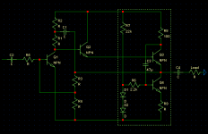
Hello. Adding a pseudo-CCS to your amp like below should help PSRR as well as increase load driving capacity (which might make it sound better).
The value of R9 should be calculated as follows:
divide 0.6/the current through R6 (in your schematic) and make this the value of R9 (in my schematic). I never heard the quiescent current specified in the above posts so I cannot do this for you.
I would advise you ask someone more in the know about this since I am subject to errr.
Also, do you fully disconnect the transformer when you switch to battery supply? It shouldn't happen with toroidal trafos but with the standard E-core you can get EMI from nearby equipment...
Hope this helps reach a viable solution,
- keantoken
Attachments
keantoken said:Hello. Adding a pseudo-CCS to your amp like below should help PSRR as well as increase load driving capacity (which might make it sound better).
The value of R9 should be calculated as follows:
divide 0.6/the current through R6 (in your schematic) and make this the value of R9 (in my schematic). I never heard the quiescent current specified in the above posts so I cannot do this for you.
I would advise you ask someone more in the know about this since I am subject to errr.
Also, do you fully disconnect the transformer when you switch to battery supply? It shouldn't happen with toroidal trafos but with the standard E-core you can get EMI from nearby equipment...
Hope this helps reach a viable solution,
- keantoken
Thank you Keantoken.
I just have to get some new veroboard or such to do a second prototype...
D
Your welcome.
Also, bypassing the 470uF cap with a smaller non-electrolytic (ceramic, not a can) may help high-frequency response just a bit since electros have internal resistance and for larger ones, the inductance caused by the rolled plates might be a problem.
I would also suggest bypassing electros in the PSU as well. This might help filter out higher frequency EMI without having to add an expensive .5 ohm resistor or inductor in series with the load (your amp).
Wait for the pros to correct me though before you do something bad. 🙂
- keantoken
- Status
- Not open for further replies.
- Home
- Amplifiers
- Solid State
- Regulated DC PSU - Plain and simple please?