Two reasons... most important was that soundwize, my dac could not compete with Danny's dac and as you know he has a heavily modified V1 (which doesn't have the big ceramics). Adding more capacidance to Vref did not help in a significany way neither. Secondly, I don't like ceramics in the signalpath and other people also reported improvement without them (only the big ones!). I do however understand the need for the small ones close to the shift registers and I will not touch these. For me, this is a good step up to the stock version... I dare to say another level. YMMV...
If you try, one good advice: use two slodering irons if you don't have special tools... if you are a bit handy, you can just heat up both sides at the same time and in less than a second you just lift the cap from the board without any harm. I re-used one of them for my oscillator rcrc filter and would be able to put them all back without problem.
Just so I understand correctly - you did remove the 12 ceramic caps at the shift register and replaced them with polymer? This does qualify as adding capacitance to Vref, doesn't it? Did you remove any other ceramic caps?
Also, these are power supply decoupling caps, they are not in the signal path, are they? The only ceramics in the signal path as far as I know are very small npo types to remove RF.
Also, these are power supply decoupling caps, they are not in the signal path, are they? The only ceramics in the signal path as far as I know are very small npo types to remove RF.
Indeed, only removed the 12 big ones (150uF if I remeber well). Yes I added 12x680uF instead, as close to the pcb as possible. I did not remove other ceramics, I added small NPO ceramics to the existing caps in the purely digital part... just because it makes me sleep better at night.
Right, but signal is modulated power supply. Cap in the power supply decoupling or in the signal, for me result is kind of the same.
Right, but signal is modulated power supply. Cap in the power supply decoupling or in the signal, for me result is kind of the same.
Indeed, only removed the 12 big ones (150uF if I remeber well). Yes I added 12x680uF instead, as close to the pcb as possible. I did not remove other ceramics, I added small NPO ceramics to the existing caps in the purely digital part... just because it makes me sleep better at night.
Right, but signal is modulated power supply. Cap in the power supply decoupling or in the signal, for me result is kind of the same.
Paralleling caps of different size and make up can be very problematic because of potential resonances in the impedance response. I've specifically seen problems created by paralleling small npo ceramics with big X7R etc. types (can't remember where though)...
I realized the polymer cap I added to the regulator input was overvolted so replaced it with panasonic FR of even bigger capacitance. I think (imagine?) it doesn't sound as good this way... have ordered polymers with appropriate voltage now and will add those to all my DAM1021 PCBs.
Upgrading vref buffers from rev1 to rev3
Hi Soren,
dam1021 rev7 sounds very exciting! Looking forward to getting one. This means I now have to upgrade my virgin rev1 board, the difference will be too obvious otherwise 🙂
Caught up with the posts since 2015 (took a while) and I see that rev1 vref can be upgraded to rev3, great!
I’ve got some simple questions for you though:
1. Would 1/6W resistors be OK? Especially the 301R one, that’s the only power rating I can find that one in.
2. I think “1K00” means 1 kOhm resistor with 0.5% tolerance. Does the tolerance for the others matter?
3. Would there be a difference in performance between using a single capacitor (eg. 330uF electrolytic stacked on the existing 22uF output capacitor) and using multiple capacitors (eg. 3x100uF added near the shift registers)? Installation convenience is not an issue.
4. Are very low ESR (5 mOhm) electrolytic caps OK? (I remember seeing a post by you warning against too low ESR, but that might be for older versions of vref, not sure). If not, what minimum ESR value would you recommend for the single cap and the 3x cap options above?
Many thanks
Hi Soren,
dam1021 rev7 sounds very exciting! Looking forward to getting one. This means I now have to upgrade my virgin rev1 board, the difference will be too obvious otherwise 🙂
Caught up with the posts since 2015 (took a while) and I see that rev1 vref can be upgraded to rev3, great!
For people who want to use two boards from different production lots in balanced mode here is how each of the four vref buffers look like from the factory:
Original rev1: 10R series resistors, 22 uF output capacitor, 330 pF feedback capacitor and 499R feedback resistor
Factory upd rev1 and prod rev2: 0.1R series resistor, 47 uF output capacitor, 499R resistors mounted in both capacitor and feedback resistor position, creating an effective 0.050R vref buffer output impedance.
Prod rev3: 0.1R series resistor, 47 uF + 3x 100 uF output capacitors, 1K00 resistor mounted in feedback capacitor position (orange), 301R resistor mounted in feedback resistor position (yellow), creating an effective 0.025R vref buffer output impedance.
I’ve got some simple questions for you though:
1. Would 1/6W resistors be OK? Especially the 301R one, that’s the only power rating I can find that one in.
2. I think “1K00” means 1 kOhm resistor with 0.5% tolerance. Does the tolerance for the others matter?
3. Would there be a difference in performance between using a single capacitor (eg. 330uF electrolytic stacked on the existing 22uF output capacitor) and using multiple capacitors (eg. 3x100uF added near the shift registers)? Installation convenience is not an issue.
4. Are very low ESR (5 mOhm) electrolytic caps OK? (I remember seeing a post by you warning against too low ESR, but that might be for older versions of vref, not sure). If not, what minimum ESR value would you recommend for the single cap and the 3x cap options above?
Many thanks
Hi Leehan,
For a V1 board, I would go for the transistormod and extra caps for the vrefs and clock.
Start reading the post from Berny and me, starting only a few pages back.
That will transform your dam v1 drastically, in a good way 🙂
For a V1 board, I would go for the transistormod and extra caps for the vrefs and clock.
Start reading the post from Berny and me, starting only a few pages back.
That will transform your dam v1 drastically, in a good way 🙂
correct me if I am wrong guys, but... these transistors work as the emitter followers, and then on the emitter leg, there is plenty of capacitance, like 10mF or so?
But why not add some nice capacitor on the transistor base, use a Darlington (or Sziklai) that would be something called the capacitance multiplier by a factor of beta1 * beta2 and we don't need to use these caps for Vref?
I need to simulate it...
EDIT: OK, it won't help :/ there would be a peak at around 9kHz :/
Last edited:
Hi Leehan,
For a V1 board, I would go for the transistormod and extra caps for the vrefs and clock.
Start reading the post from Berny and me, starting only a few pages back.
That will transform your dam v1 drastically, in a good way 🙂
Hi Danny,
It was either the transistor mod or the rev3 mod for the vref buffers for me indeed. A few things put me off the transformer mod though:
1. Original transistors are obsolete and I am not capable of finding any replacements.
2. Paul mentioning increased 2nd order harmonics and other issues on his website (not sure if he actually implemented this or it was just simulated). This actually makes me wonder if this is the reason people like it more than other mods.
3. People who did the transistor mod usually using large amounts of capacitance. I have the impression that any capacitor will inflict its own signature on the overall sound in its own way. So the less of them the better. At this moment I think I prefer the minimum amount suggested by the official solution.
4. Absolute lack of objective measurements of final implementations for the transistor mods (only some early sim results with which Paul quickly disagreed with their optimism).
I am sure you arrived at a combination of mods you are very happy with and I admire you 🙂 But it took quite an effort (I read most of your posts enthusiastically) and I simply don't have the capacity to try that many of them.
Ah, more importantly, current rev1 board will be relegated to office use after the mods and hopefully be replaced by rev7 in its main duty 🙂
Thanks again for the suggestion, I appreciate it.
correct me if I am wrong guys, but... these transistors work as the emitter followers
They are followers but the base is driven from an opamp output and the transistor is included in the opamp nfb loop, so it resembles a super regulator topology.
1. Original transistors are obsolete and I am not capable of finding any replacements.
Practically any low power Si transistor will work.
Hi leehan, ripson,
As long as you upgrade the vrefs of the v1 board,
whether it's the lowres, factory or transistor mod.
It's a big improvement over the stock v1.
Check also the output of the 3.3v regulator with a scope and add some caps as Berny mentioned.
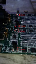
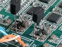
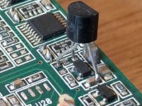
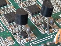
Here are some pics of the transistor mod.
As long as you upgrade the vrefs of the v1 board,
whether it's the lowres, factory or transistor mod.
It's a big improvement over the stock v1.
Check also the output of the 3.3v regulator with a scope and add some caps as Berny mentioned.
Here are some pics of the transistor mod.
Attachments

They are followers but the base is driven from an opamp output and the transistor is included in the opamp nfb loop, so it resembles a super regulator topology.
Thanks for that, that explains why adding a cap to the base makes things worse 🙂
I have analyzed the Vref circuit. That was probably done before but I could not find it, this thread is so huge.🙂

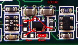
I don't want to make any changes that I don't understand so I did a simulation. Shorting or leaving 68A (499 Ohms) resistor doesn't change much. It gives a small difference (in a favor of leaving) in the region of 100MHz. I would add at least a 2000uF low ESR cap on the emitter.
This mod removes the peak at about 142kHz (at least in the simulation)
I will apply these changes tomorrow and let you know if I hear any difference. For now, I'm using a simple LM317/LM337 supply but ordered Salas UltraBIB.
Hi ripson,
Here are some ltspice sims of the vref that I have,
maybe these can help.
Thank you very much Danny. I'm going to have a look today.
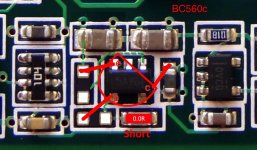
I have completed the Vref mod by adding BC550C and BC560C (hfe=450-500 at about 2mA) and a single polymer 2200u/6.3 cap per rail from Wurth. I left 499 Ohm feedback resistor.

Does it sound better? Well, it doesn't sound worse for sure. But if there is a difference it's not as obvious as after bypassing the output opamps and then removing the blocking 1.2nF caps (I don't need them as I'm using First Watt F2J connected directly to the DAC - amp with no feedback, single stage, the JFET input capacitance stops HF anyway). Maybe it's slightly more defined, crispier, less harsh, but it's easy to self-suggest 🙂
There is a lot of micro details, great 3D imaging, I really love it. But I am not 100% sure if that is thanks to the Vref mod 🙂
Last edited:
Very nice 
Years ago, when I first listened to the stock V1 it didn't have a chance against other DACs during a listening session, it sounded flat, 2D.
After those mods it transformed, got that 3D sound and surpassed those other DACs.
Another easy mod you can do is an extra cap after the 3.3v regulator,
you can even use the jumper J9
I really love it. But I am not 100% sure if that is thanks to the Vref mod 🙂
So, you don't hear a 'clear' difference before and after... then you should stop modding. 🙂 Or get to re-know your dac between each mod. ;-) That is what I try to do, but it is true I did the whole cap mod (Vref and 3.3V at once myself). Anyway, as Danny said, check that 3,3V supply.
Last edited:
Another easy mod you can do is an extra cap after the 3.3v regulator,
you can even use the jumper J9
The reason why I haven't added any cap to J9 is that my voltage meter measured 0V there :/
- Home
- Vendor's Bazaar
- Reference DAC Module - Discrete R-2R Sign Magnitude 24 bit 384 KHz