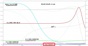
DAM Super Regulator
I can make a super regulator simply adding 1 transistor. Is better than a separate power supply and Floating mass.
It is similar to that proposed by AECM but short in the R sensor Instead in feedback capacitor.

The output impedance similar that a Super-Regulator Jung. And haven't oscillation, is stable.

I can make a super regulator simply adding 1 transistor. Is better than a separate power supply and Floating mass.
It is similar to that proposed by AECM but short in the R sensor Instead in feedback capacitor.
The feedback at the emitter of transistor is a Sulzer Super-Regulator. Provides +4 and -4 vol. Vout Instead of +3.4 and -3.4 vol. Vout proposed by AECM circuit.After several transistor based schemes, I came to a final one. And from my point of view it looks the best one in my oscilloscope. Even better than Soren’s mod proposition.
The last scheme
An externally hosted image should be here but it was not working when we last tested it.
I used the original buffer scheme, but modify it to become as a pure follower.
The output impedance similar that a Super-Regulator Jung. And haven't oscillation, is stable.
Attachments

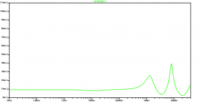
It would be interesting to have the power supply related plots up to 3MHz, as the load of the ladder heavily fluctuates (in a nonlinear way) with the final sample frequency.
I can make a super regulator simply adding 1 transistor.
Very nice and simple, maybe I'll try that.
For the moment I'm on 499/499/0.01 47uf + 9x680uf + 2x6.8uf mkt and some extra clock caps.
Last edited:
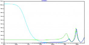
3 MHz. Impedance is made by capacitors.It would be interesting to have the power supply related plots up to 3MHz, as the load of the ladder heavily fluctuates (in a nonlinear way) with the final sample frequency.
I look through the oscilloscope and does not oscillate.
Attachments
Last edited:
Oneclock,
How is the sound after mod with transistor, if compare it with other mod. Big Step or only improve in figure?
How is the sound after mod with transistor, if compare it with other mod. Big Step or only improve in figure?
3 MHz. Impedance is made by capacitors.

I look through the oscilloscope and does not oscillate.
Hi again Soren, another practical question. In balanced mode, what would be the most appropriate way to directly drive a set of headphones wired as balanced using the onboard opamps? Is there a way to run the buffered output bridged?
Last edited:
Did you connect the positive supply to the digital isolator from the same supply used by the QA550?
No. I connected a LT1084-3.3V regulator after the LT1084-12. The 3.3V supplied to the digital isolator and the 12V supplied to the DAM1021.
To my knowledge the QA550 outputs the i2s data with 16bit word length, but soekris mentioned the dam needs 32bit.
Thanks for your input. This may explain why DAM1021 does not like QA550 to be its partner under I2S connection.
3 MHz. Impedance is made by capacitors.
I look through the oscilloscope and does not oscillate.
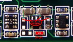
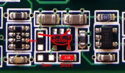
@Oneclock, did you also try simulation with the original 500 ohm sense resistor still in place? It should lead to better balancing of inverting and non inverting input bias current. Also one less component to change...
Yes.🙂@Oneclock, did you also try simulation with the original 500 ohm sense resistor still in place? It should lead to better balancing of inverting and non inverting input bias current. Also one less component to change...
In the impedance simulation is identical result a short or 500 Ohm. Then you do not have to do anything, resistance is OK. Short is no necessary.
This is the correct image.It would be interesting to have the power supply related plots up to 3MHz, as the load of the ladder heavily fluctuates (in a nonlinear way) with the final sample frequency.
Attachments
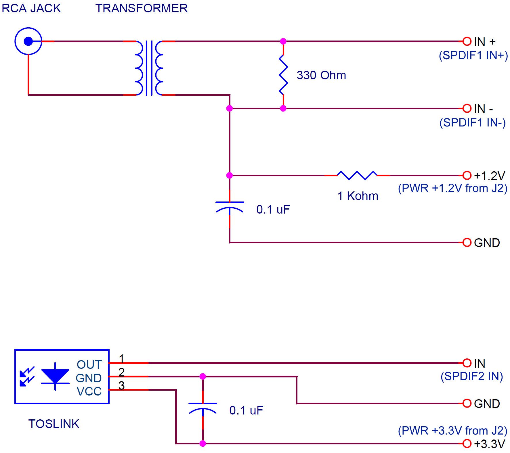
Can I use voltages from J2 to power Coax & Toslink inputs ?
Yes, you can.
Hello everybody,
Someone knows how to set the delay in the FIR filter for the dam1021?
AFAIK there is no such functionality implemented in the current firmware.
Oneclock,
How is the sound after mod with transistor, if compare it with other mod. Big Step or only improve in figure?
I think it's an improvement.
I will compare with other DAM1021 mod.1 0.1 / 0/499 4x 1000uF (ESR 0007). It has spectacular treble that mod.1. Now also has spectacular bass. But I hope to compare with other people. It may be suggestion.
Last edited:
Yes I know that 🙂, but at HIFIDUINO it is said:Yes, you can.
"I took a closer look at the J2 connections on the backside and the board and the +/- analog power connections are connected to the power lines after the RC filter. If you power through J2, there will be a 12 ohm resistor to the filter/smoothing caps. This would not destroy the board, but it is not the right design/thing-to-do either. Thus there is no good reason to power through J2.
- Home
- Vendor's Bazaar
- Reference DAC Module - Discrete R-2R Sign Magnitude 24 bit 384 KHz