N....
TNT - I do not think one can divorce the ground from the circuit. Sure would make things easier ...
Well this C marries the signal to ground above f0 and divorce it from ground below f0. A divorce can be hard. During all its aspect, it shall stand there unaffected, solid and with integrity despite attacks with different frequencies and energy. The marriage however is easy, its beyond pain and perception (as we can't hear that high freq) so here problems are unheard of (pun intended).
A bad C involves the ground in the divorce - that is a problem yes.
//
Last edited:
SOEKRIS,
I appreciate your comments but I did intend my comments to concern ceramics in the signal path. I use them in power supplies - haven't reached the nirvana stage where I think they should all be returned to the earth.
I do not doubt the NPOs are better than what I had used in the past; the ones responsible for my low opinion.
I see this quality of dielectric is not too expensive in 1.2nF - are you using these on the boards?
THANKS for the update on the vREF values!
Take care,
TNT,
I am not qualified to argue these points but I figure what is being segregated has to go somewhere and that is into the ground which is, from what I can tell, part of the circuit.
I readily admit I look at these things empirically conceptually with very little knowledge of circuit design technology. It is all magic to me with supernatural forces creating unpredictable behaviours! More fun that way ... especially when you do not have an oscilloscope or any of that kind of stuff.
Ok, but the c in this case starts to conduct to ground above its frequency - and is it sits in parallel with the output, thats how it does it filtering thing. Obviously it does not do it below or we would not hear any music.
//
//
SOEKRIS,
I appreciate your comments but I did intend my comments to concern ceramics in the signal path. I use them in power supplies - haven't reached the nirvana stage where I think they should all be returned to the earth.
I do not doubt the NPOs are better than what I had used in the past; the ones responsible for my low opinion.
I see this quality of dielectric is not too expensive in 1.2nF - are you using these on the boards?
THANKS for the update on the vREF values!
Take care,
Yes, the 1.2nF in the filters are of course NP0, so are the 470pF on the output buffers, even shows on the output buffer schematics posted long time ago....
The cap on the raw output is 470pF - right?
//
No, 1.2nF on raw output, 470pF on balanced buffers, see schematics posted long time ago, also available elsewhere, like on hifiduino....
No, 1.2nF on raw output,
would be an issue replaced with 1nF?
would be an issue replaced with 1nF?
I see that MICHAEL PERCY has a 0.001uF RELCAP tubular polystyrene/tin foil . I was thinking of using this. Adding a 200pF cap would be really clumsy.
Would be interested to know how this value was selected - is it part of a large filter scheme or is it simply a first order filter on its own?
There is only one who can answer this question!
See post #3651, just a little back.... Or look at schematics.... Or both....
It's perfectly legitimate to try without the cap altogether - most amps will have low pass filters on their inputs anyway. If it sounds better without the cap, it is better.
Sören - if I will never run in NOS mode is it then safe from a hf output perspective run without the caps (raw output)?
//
//
Sören - if I will never run in NOS mode is it then safe from a hf output perspective run without the caps (raw output)?
//
As the dam1021 oversamples to 3 Mhz there isn't any aliasing until around 3 Mhz anyway, and then not much, assuming good digital filters....
The 200 Khz filter have two purposes:
1) attenuate what's left of the aliasing and
2) limit signal slew rate on input to output buffers
So if using direct output and the following equipment don't have any problem with some 3 Mhz noise, then it's safe to remove the filter capacitors. But in my opinion the filter don't hurt, but you can of course have your opinion 🙂
Thanks Sören! I hear great differences between caps in this position. I need to try without then also. No playing: http://uk.rs-online.com/web/p/polystyrene-film-capacitors/0116240/
with MoreDAMFilters latest -3,5dB version.
Playing: Mahler: Symphony #4 In G - 2. In Gemächlicher Bewungen, Ohne Hast
Exciting, involving, real, detailed, dark as in reality, resolved, clean. Wonderful.
Best yet.
//
with MoreDAMFilters latest -3,5dB version.
Playing: Mahler: Symphony #4 In G - 2. In Gemächlicher Bewungen, Ohne Hast
Exciting, involving, real, detailed, dark as in reality, resolved, clean. Wonderful.
Best yet.
//
Attachments

See post #3651, just a little back.... Or look at schematics.... Or both....
Sure wish my memory was better. It was all there. INCLUDING the ceramic type. I need to take notes.
Thanks for your patience and take care,
C135 and C142 have no other function than reducing the high frequency noise, as long as they sit across the R-2R network you can change type, value and location to fit you, or remove them totally if you don't have any problem with high frequency noise, we're talking aliasing of the final 3 Mhz sample frequency....
The normal -3db cutoff is 130 Khz (625R || 1.2 nF). I don't believe anybody can hear the high quality ceramic NP0 type used at that cutoff, but this is diy....
I am without the caps. First impressions are positive. But as I said I am using headphones and not my main system.Sören - if I will never run in NOS mode is it then safe from a hf output perspective run without the caps (raw output)?
//
P.S.
I am not sure about how my class-D will accept this change.
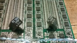
Z-foil R625
Hi there, it should be fine, my one was......
As this is my first post in this forum I would like to give a credit to all of you for unbelievable work done so far in making DAM1021 superb DAC (in my opinion very unique in the current market ……. nothing else come close- even Chord Hugo is inferior with Spartan 6 ; chip 9 , DAM have chip16 upgradable to chip 25).
Initially as I already have finished TP Buffalo III in balanced config and in good old tradition of DIY "if isn't broken, try to fix it anyway" came to conclusion that it will be better to start a new project. That is where DAM1021 intrigue me with its potential to be ultimate source of "real" sound. I will try to give a small contribution to this.
Going trough all post so far there is one thing that was overlooked and I believe by replacing it could bring performance a notch up (every db is counting ). This is resistor (two to be exact) in low pass filter R625.
As being in direct audio path by replacing it with vishay z-foil equivalent this could bringDAM1021 to a whole different level . Now most of you will (Søren, Paul?) probably say that this is overkill and it would't make any difference, maybe so, but I have already ordered 4 of :VISHAY-77442 from: Partsconnexion and will inform off outcome once is done.
Cheers
Danny
btw. for all of you struggling to find hi-rez/hi dynamic test files go to : NativeDSD and download for free (after registering) DXD file No6 : Mahler 1 finale - session recording DXD. (352.4khz)
p.s
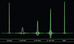
In my opinion DAM will truly shine (as did TP Buffalo III) once DSD (attachment :recording pulse response) is finally supported and as per post #109 "384 Khz sampling is more for show anyway, afaik there are no 384 Khz music files available, I could as well do 768 Khz sampling" Søren could you please, once DSD support is included, enable 768khz (future DXD format of 21th century - 44.1khz is so old as SPDF is)
thanks…….
I am without the caps. First impressions are positive. But as I said I am using headphones and not my main system.
P.S.
I am not sure about how my class-D will accept this change.
Hi there, it should be fine, my one was......
As this is my first post in this forum I would like to give a credit to all of you for unbelievable work done so far in making DAM1021 superb DAC (in my opinion very unique in the current market ……. nothing else come close- even Chord Hugo is inferior with Spartan 6 ; chip 9 , DAM have chip16 upgradable to chip 25).
Initially as I already have finished TP Buffalo III in balanced config and in good old tradition of DIY "if isn't broken, try to fix it anyway" came to conclusion that it will be better to start a new project. That is where DAM1021 intrigue me with its potential to be ultimate source of "real" sound. I will try to give a small contribution to this.
Going trough all post so far there is one thing that was overlooked and I believe by replacing it could bring performance a notch up (every db is counting ). This is resistor (two to be exact) in low pass filter R625.
As being in direct audio path by replacing it with vishay z-foil equivalent this could bringDAM1021 to a whole different level . Now most of you will (Søren, Paul?) probably say that this is overkill and it would't make any difference, maybe so, but I have already ordered 4 of :VISHAY-77442 from: Partsconnexion and will inform off outcome once is done.
Cheers
Danny
btw. for all of you struggling to find hi-rez/hi dynamic test files go to : NativeDSD and download for free (after registering) DXD file No6 : Mahler 1 finale - session recording DXD. (352.4khz)
p.s
In my opinion DAM will truly shine (as did TP Buffalo III) once DSD (attachment :recording pulse response) is finally supported and as per post #109 "384 Khz sampling is more for show anyway, afaik there are no 384 Khz music files available, I could as well do 768 Khz sampling" Søren could you please, once DSD support is included, enable 768khz (future DXD format of 21th century - 44.1khz is so old as SPDF is)
thanks…….
Attachments
It's perfectly legitimate to try without the cap altogether - most amps will have low pass filters on their inputs anyway. If it sounds better without the cap, it is better.
I ran mine for quite some time without the cap with no issues into a class ab fc100. Note that as this cap is in parallel with the raw output it can easily be relocated to the input of any upstream bufferyou may want to use. In my case I am using a dcb1 and have subsequently
fitted 1200pf silver micas with no audible degradation.
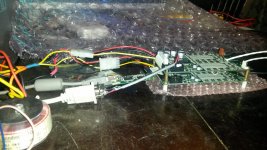
DAM works OK with diyinhk XMOS DSD usb I2S converter? I'm a bit confused, because this converter needs 3.3V to operate, am I right? So, I can plug in dedicated external 3.3V to USB converter and another dedicated external 3.3V to DAM? Then, I can connect BCK, LRCK and DATA to DAM and that's it?
Regards
EDIT: My plan was to use WaveIO. Power it via external dedicated 5V PSU. Connect it to DAM via unisolated I2S lines and power the DAM with additional external dedicated 3.3V PSU on I2S lines. Will that work? I don't see a point in using isolated I2S on WaveIO and then again isolated I2S on DAM.
Last edited:
- Home
- Vendor's Bazaar
- Reference DAC Module - Discrete R-2R Sign Magnitude 24 bit 384 KHz