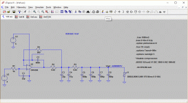
Yes, I've calculated them according the application noteAre you using the 0.68uF cap in the feedback loop instead of a jumper?
Did you try the jumper and find you preferred using this cap?
I also did some simulations in Ltspice and a large capacitors bank (3000uF) with a 0.68uF compensation cap gave me a better result in the simulations.
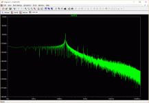
The series resistor is 0.01 and a guess of the PCB trace resistances.
The FFTs are taken between R2 and R3.
I also have some jumpers that I will maybe install later, but my simulations say no, first enjoying the DAC some time before back to SMT soldering 🙂
Attachments

Last edited:
DAM is isolated. Dubbel isolation seems like overkill and would require yet one separate power feed. Go for one. I suggets the DAM one.
So the non-isolated Wave-IO one. But use galvanically separated power feed for each!!!
//
So the non-isolated Wave-IO one. But use galvanically separated power feed for each!!!
//
I would assume that means separate secondary transformer windings and power regulators for the 5V USB and 3.3V isolater power supply, right?DAM is isolated. Dubbel isolation seems like overkill and would require yet one separate power feed. Go for one. I suggets the DAM one.
So the non-isolated Wave-IO one. But use galvanically separated power feed for each!!!
//
Thanks the help!
Just a tip. If you guys are using the WaveIO just for the USB to I2S functionality for the DAM1021, email Lucian and he'll give the option of leaving just those components on the board which reduces the price to 87.6EUR + shipping and fees
Just a tip. If you guys are using the WaveIO just for the USB to I2S functionality for the DAM1021, email Lucian and he'll give the option of leaving just those components on the board which reduces the price to 87.6EUR + shipping and fees
danny66,
Very interesting. I know there had been speculation about this with Paul. If you had brought this to attention before I am sorry I missed it.
What are you using for this capacitor?
Thanks and take care,
Very interesting. I know there had been speculation about this with Paul. If you had brought this to attention before I am sorry I missed it.
What are you using for this capacitor?
Thanks and take care,
Well, when I have some time free Ι will explore them...
One question about the caps. Can I remove the caps from C135 and C142 and add the caps over the RCA outputs? I have removed the buffer output opamps
One question about the caps. Can I remove the caps from C135 and C142 and add the caps over the RCA outputs? I have removed the buffer output opamps
PanagiotisPapadakos... some new -3,5 dB filters for u a moradam👎filters 😉
Waddaya think?
//
C135 and C142 have no other function than reducing the high frequency noise, as long as they sit across the R-2R network you can change type, value and location to fit you, or remove them totally if you don't have any problem with high frequency noise, we're talking aliasing of the final 3 Mhz sample frequency....
The normal -3db cutoff is 130 Khz (625R || 1.2 nF). I don't believe anybody can hear the high quality ceramic NP0 type used at that cutoff, but this is diy....
The normal -3db cutoff is 130 Khz (625R || 1.2 nF). I don't believe anybody can hear the high quality ceramic NP0 type used at that cutoff, but this is diy....
So the idea is that if someone is not using a NOS filter he can just remove the cap, right?C135 and C142 have no other function than reducing the high frequency noise, as long as they sit across the R-2R network you can change type, value and location to fit you, or remove them totally if you don't have any problem with high frequency noise, we're talking aliasing of the final 3 Mhz sample frequency....
The normal -3db cutoff is 130 Khz (625R || 1.2 nF). I don't believe anybody can hear the high quality ceramic NP0 type used at that cutoff, but this is diy....
I think the view of that a cap that's creating a LP filter only affects things above it's stopband it's quite naive. It's duty is to do nothing in the oassband also which might not be an easy accomplishment. Siren I wish you experiment with caps and hear for your self.
//
//
C135 and C142 have no other function than reducing the high frequency noise, as long as they sit across the R-2R network you can change type, value and location to fit you, or remove them totally if you don't have any problem with high frequency noise, we're talking aliasing of the final 3 Mhz sample frequency....
The normal -3db cutoff is 130 Khz (625R || 1.2 nF). I don't believe anybody can hear the high quality ceramic NP0 type used at that cutoff, but this is diy....
Minor calculation error, the -3db cutoff for that filter is 212 Khz....
I agree with TNT since all of the signal will be passing through the capacitor whatever artifacts the dielectric leaves behind will affect everything and there is no question ceramic caps have their place but not in the signal path.
When one looks at the wacky non-linearity of ceramic dielectrics it is a surprise there aren't more problems heard - which is SOEKRIS's point, I suspect, but nonetheless using something better has to be, ... better.
Flikoman, I think I am correct in telling you the new boards use 0.1R resistors and jumpers where the feedback loop capacitors used to be.
Well I have to object to pass through... Frequently above f0 yes. Below no. It it can still do damage below of course.
Flikoman, I think I am correct in telling you the new boards use 0.1R resistors and jumpers where the feedback loop capacitors used to be.
So, that's a good thing or? 🙂
No one seems to be sure!
moreDAMfilters/Paul has found other values to measure better - can't remember if these were simulations or actual measurements.
He found that 0.01R was better with more supply bypass capacitance and there is the question of whether the jumper or a different value of capacitance in the feedback loop is best.
There is no question that the values SOEKRIS is using are a vast improvement over the original based upon many comments and going beyond this could be considered vanity or lily gilding by most. But then there are those of us who are vain audiophiles who are sure we can hear the flies buzzing around the recording hall without wondering why anyone would want to hear such a thing.
See above posts from danny_66 who makes a good case for a feedback loop capacitor.
TNT - I do not think one can divorce the ground from the circuit. Sure would make things easier ...
Last edited:
I agree with TNT since all of the signal will be passing through the capacitor whatever artifacts the dielectric leaves behind will affect everything and there is no question ceramic caps have their place but not in the signal path.
When one looks at the wacky non-linearity of ceramic dielectrics it is a surprise there aren't more problems heard - which is SOEKRIS's point, I suspect, but nonetheless using something better has to be, ... better.
You should investigate the different ceramic capacitors before using words like "wacky"....
NP0 are actually very good, X7R are good but use with care in audio path, X5R are very good for power decoupling, Y5V for, hmm, can 't really find any good use for them, maybe "wacky" is the right word for the Y5V type....
Flikoman, I think I am correct in telling you the new boards use 0.1R resistors and jumpers where the feedback loop capacitors used to be.
Actually I have improved the factory circuit a little since for rev 2, using 0.1R series resistors and 500R feedback instead of the capacitor, then you get 0.05R output impedance. The rev 2 dams then have around 80uF of capacitance on each vref rail. Considering that each LVC595 then add 0.3R internal then it's a good design.
- Home
- Vendor's Bazaar
- Reference DAC Module - Discrete R-2R Sign Magnitude 24 bit 384 KHz