I agree, DC compensation is not a uncorrelated noise compensation . In general, I am very pleased that in your person I found an audio circuit engineer who is well versed in the most complex but also in the most interesting section - of noise analysis.it is generally rather worse than that
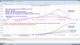
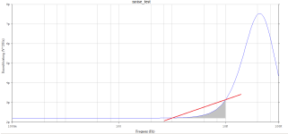
 I am attaching a screenshot of noise analysis slightly off topic, but also interesting and related to phono preamps - this is a comparison of a standard 47 kOhm input, a "passive cooling" of 150 kOhm, and two "damping resistance" options with a resistance of 8 kOhm. The first is simply 8 kOhm with a corresponding roll-off of the frequency response above Lcart/Rin=75 microseconds (2120 Hz), and the second is 8 kOhm with a 75 μs RIAA correction eliminated from the phono corrector
Attachments
IMHO better see my masterclass "Noise in audio circuits" [Please take a detailed look at the source code.
noises_n_n.exe(...) then use superposition to combine them all at nodes (...)
takes all this into account, i.e. for the user who does not know the programming: the output of the third line uses the superposition principle completely, therefore the SNR there is decisive.
@Nick Sukhov
Please do us all a big favor and copy the pages of your book from 1985 mentioned in the video - and post them here as a PDF document excerpt.
thx,
HBt.
Please do us all a big favor and copy the pages of your book from 1985 mentioned in the video - and post them here as a PDF document excerpt.
thx,
HBt.
I would like to conclude this topic on the impedance of an average MM generator as follows:
- Rp(f) = 1,0589*10^-2 [sec/kOhm] * f^0,94012 [1/sec] & Lp(f) = 3,3862 [^sec/H] * f^-0,2359 [1/sec]
- Rs(f) = 8,4975*10^-4 [sec/kOhm] * f [1/sec] + 0,1264 [kOhm] & Ls(f) = 0,4994 [sec/H] * e^(-2,5993*10^-5 * f) [1/sec]
The validity range of this regression analysis from six to five support points extends over two decades. These approximations are based on my old AT420E/OCC. I have taken the values directly from the table of values for an equivalent voltage source:
0,1kHz
397,7 Ohm + j 327 Ohm
10kHz
7k824 Ohm + j 21k564 Ohm
This is the source impedance that our input of the MM-EQ sees - in terms of magnitude |0k515 Ohm| to |22k94 Ohm| (...)
I posted this in the OREAD thread, maybe the approach will help one or the other in future cases ..!
OK, please see it in attached file. But this book is not only mine, and also three of my friends - Vadim Kolosov, Sergey Batti and Alex Chupakov. I wrote the second chapter (pp. 21-95) and did the general content.@Nick Sukhov
Please do us all a big favor and copy the pages of your book from 1985 mentioned in the video - and post them here as a PDF document
Attachments

Quelle
"|Zcartridge|" times ...Now apply a Norton-Thévenin transformation to the cartridge impedance and the current source in parallel with it, and you end up with part D, which has a noise voltage inR2 Zcartridge directly in series with the Thévenin voltage of the cartridge. The spectral density is |Zcartridge| √(4kT/R2) (and the power spectral density is therefore |Zcartridge|^2 4kT/R2). Note that this increases with decreasing R2.
Nothing is easier to implement in the noise_n_.exe program than this suggested transformation from the dispute thread.
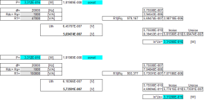
84pA * sqrt[ (Rcart)^2+(omega*Lcart)^2 ] =Uth
U_noise_47k = Uth * R2 / sqrt[ (Rcart+R2)^2+(omega*Lcart)^2 ] = 0.9709 * Uth
vs.
47pA * sqrt[ (Rcart)^2+(omega*Lcart)^2 ] =Uth
U_noise_150k = Uth * R2 / sqrt[ (Rcart+R2)^2+(omega*Lcart)^2 ] = 0.9925 * Uth
518.9nV vs. 299.03nV
bw=20kHz
The all-important question is: may* (here) R2 be transformed into a substitute noise current source for this mesh, viewed as a ring.
*is it permissible?
If this is the case, then a (here) R2, as a parallel part of the input resistance of our amplifier, naturally leads to this gain! Unoise at the input of the system would then be inversely proportional to R2||r_inp, so ~1/R2 !
because now R2 is typified as the source of i_n in [A/sqrt(Hz)].
tbc
If you comprehend the true input of the system is v_catrridge, not amplifier input, it became not so crazy. It's noise, my friend, and even the sum of two uncorrelated noises is exactly equal to their difference !Unoise at the input of the system would then be inversely proportional to R2

And here is the paradox
R2 in Marcel's nomenclature is simply not a noise-current source of the ring (or the mesh), but both active (working) resistors are noise-voltage sources - and only these are correctly transformed into current source models, whose currents can then be geometrically added to a total current ..!
u_noise is now proportional to this current or also to the equivalent resistance (formed as Rdc||R1, in my nomenclature).
If Z(jOmega)= Rcart+jXcart were noise-free, then the Sukhov&Marcel-Story would be correct, but then you could also turn it around and consider R1 (or R2) as noise-free and
i_n = sqrt(4*T*k*df * Rdc)/Rdc ...
and so on.
Attachments
howplease?(...) It's noise, my friend, and even the sum of two uncorrelated noises is exactly equal to their difference !
"C = sqrt( A^2 + B^2) is also C = A - B"
Shure???
🙄😒
No,If you comprehend the true input of the system is v_catrridge, not amplifier input, (...)
the transducer-coil is the SignalSource and all that follows is the AC impedance of the amplifier (the input). Rdc , the DC resistance of the coil wire is of course a component of the signal source (at the input of the amplifier).
kindly,
HBt.
Two uncorrelated noise voltage sources arithmetically added or subtracted would lead to the same random chaos, that's true. They are not phase-locked to each other.If you comprehend the true input of the system is v_catrridge, not amplifier input, it became not so crazy. It's noise, my friend, and even the sum of two uncorrelated noises is exactly equal to their difference !
If we want to consider the ideal voltage source V_cart, which in reality does not exist, as the ultimate input of the entire system - whether this is permissible is still up in the air - then we must of course move (all) the (noise) sources to the far left.
Dear Nick S.,
Thank you for your patience with me. If this kind of source shifting really needs to be applied here, then you (and Marcel vdG) are absolutely right.
Does the experts agree on this point, or is it a controversial issue? If it's undisputed, then it applies to every pickup, including the pickup head in a magnetic tape recorder.
greetings,
HBt.
Last edited:
The key point, however, is that we need to shift (let's just say bundle) the equivalent total (voltage) noise to the input of the operational amplifier.

When will the knot of this paradox finally be untied?
HBt.
Note:
The OP is currently considered noise-free, so the gray area represents the "resulting thermal (voltage) noise" of the pickup plus cable plus termination.
When will the knot of this paradox finally be untied?
HBt.
Note:
The OP is currently considered noise-free, so the gray area represents the "resulting thermal (voltage) noise" of the pickup plus cable plus termination.
Last edited:
transferring noise sources from one place to another requires additional recalculations according to Kirchhoff's and Ohm's rules; in my opinion, it is much simpler, faster and more error-free to assign these operations to a circuit simulatorthen we must of course move (all) the (noise) sources to the far left
If we consider the operational amplifier as ideal, i.e. completely noise-free, and the larger of the two thermally noisy resistors as the drive (in the ring), i.e. a current source, and the much smaller resistor as a voltage source with (noise-free) internal resistance, then Nick&Marcel's assumption is correct.
But:

This is the common (and correct?) consideration of the simple relationships at the input of the amplifier, both noise voltages...
But:
This is the common (and correct?) consideration of the simple relationships at the input of the amplifier, both noise voltages...
That's all true, Nick.transferring noise sources from one place to another requires additional recalculations according to Kirchhoff's and Ohm's rules; in my opinion, it is much simpler, faster and more error-free to assign these operations to a circuit simulator
Yes, a simulator, and especially the MC-12, is great.
Still, for a basic understanding, the rocky road is the best, the one with the later, very steep learning curve.
The weighting factors are really not that trivial to determine; source shifting is very abstract. But, You can find them in textbooks that deal precisely with this topic. Okay, I admit, this model world is something for academics.
Peace,
HBt.
@PMA
The simplest thing would be a comparative measurement, not a comparison of a digitized LP playback! So we need Pavel's help: he can increase the termination to 150k in his test setup (OpenPhonoOne - of course, C1 must be removed and the MM cartridge (magnetically shielded) must be connected directly, without a cable).
The simplest thing would be a comparative measurement, not a comparison of a digitized LP playback! So we need Pavel's help: he can increase the termination to 150k in his test setup (OpenPhonoOne - of course, C1 must be removed and the MM cartridge (magnetically shielded) must be connected directly, without a cable).


- Home
- Source & Line
- Analogue Source
- Quick comparison -> OP-Amp Noise -> Simplified calculation