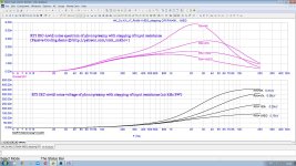
+12dB RIAA-Filter-Gain over the hole audioBW, approx 54dB SNR.The 41.534dB of the third output line are correct, I'm sorry to say.
So in conjunction with the various limitations of the record medium and the fact that Rq will never be 100k, we can of course implement an AllInOne EQ with the OP27. But it works much better with the OPAxxx, which has already been mentioned countless times. Whether we can really make out the sonic differences is written in the stars.
Thank goodness this thread is about the intuitive, but nevertheless correct, theoretical understanding of the phenomenon of noise! Four crucial passive components and one active component with two inputs and one output, that's what it's all about.
HBt.
TYPOThe solution to the puzzle can only be:
Rq increases with frequency, whilejOmegaLtc decreases, i.e. with all the nice measurements (which are not wrong!) the influence of the complex signal source impedance (on the heard result) remains uncovered. And Richard L. will have recognized this on his countless dives.
Rq increases with frequency, while Ltc decreases ...
OP27 is really 5534 with EVIL input current cancelling so usually just slightly worse than 5534 which, as we've seen, is really quite good. It would be the same as 5534 if the impedances on both input pins was sorta the same but you don't have that in a single OPA RIAA stage.Pavel compares ...
Real world measurements with the well-known Shure MM shows no problems with the OP27, and that drives me crazy, because the measurement result should have been worse - considerably worse, also with the LT1028 as deputy of his guild.
I apologise for saying it is CRAP like LT1028. Must have been thinking about another OPA, perhaps AD 797 which Guru Wurcer would tell you is NOT for RIAA MM 😲
Let's see what good or bad effects equal impedances as the source of all evil have on the inputs compared to the unbalanced version? As a sporting challenge, let's take a look at the well-known data sheets of AD and LT, text and graphics are sometimes contradictory or unfavorably formulated in connection with an MM as a source and full audio bandwidth.
Attachments
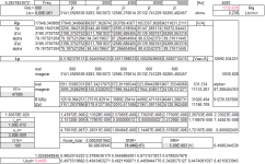
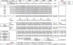
Now here is a spreadsheet, it confirms what we all know 150k is greater than 47k and therefore his rushing contribution is also, in the first instance, higher.(...) or even a spreadsheet, then it would run on other OS's.
But, a calculation of this kind still neglects three points - later I will submit a complete calculation, which takes into account the influence of the complex voltage division at both inputs, related to all variables to be considered.
Among other things, Cp and the RIAA network are still missing in the negative feedback branch, as well as the +1 error.
Attachments
Marcel, you know that for the compensating and compensated input currents, only the oppositely directed DC components are subtracted, while the uncorrelated noise is always RMS added. With perfect symmetry, the DC currents are reduced to zero, while the noise is increased by a factor of 1.41 or 3 dB.You can therefore expect a substantial common-mode component of the input noise current.
Figure 27 shows a noise measurement circuit that cancels the common-mode component of the input noise current, leading to unrealistically good values

Wrong. see attached file. You must keep in mind cartridge inductane @ input + RIAA + A(or ITU-R)weightingwe all know 150k is greater than 47k and therefore his rushing contribution is also, in the first instance, higher.
Attachments
Please don't get me wrong Nick S.,Wrong. see attached file. You must keep in mind cartridge inductane @ input + RIAA + A(or ITU-R)weighting
under no circumstances do I want to start the old dispute all over again. I'm only interested in the discovery process, in untying the knot. The node consists of the fact that the thermal noise, the average amount we consider and name as equivalent noise voltage: ((4*K*T*BW) * R)^0.5 and this part is definitely getting bigger!
I also weigh in here, but indirectly.
greetings,
HBt.
Attachments
The node consist of not naked input resistor 150k or 47k but with attached @ input of phonopreamp cartridge with average standardized inductance of 500 mH. It has much lower inpedance vs both of 150k or 47k, then cartridge shunts input resistor (the lower freq, the bigger shunting) with his noise current ((4*K*T*BW) /R)^0.5. After that you have RIAA with +20dB @ 20 Hz and -20dB @ 20kHz, and in the end a IEC-A weighting with -50dB @20hz and -10dB @20kHz. The noise voltage at the output of the phono preamplifier must be divided by its gain at 1 kHz to obtain the input-referred noise level (RTI). Without all of the above elements, discussions about bare resistor noise are completely meaningless.The node consists of the fact that the thermal noise, the average amount we consider and name as equivalent noise voltage: ((4*K*T*BW) * R)^0.5 and this part is definitely getting bigger!
@Nick Sukhov
If I assume that MC-12 presents us with a correct result at the end of the entire evaluation /schematic, or if you, Nick, as a human, present a manual calculation that also confirms the result, then the fundamental error lies in the general transformation of the equivalent two-terminal-pole at the positive input of our operational amplifier.
And that's exactly where it lies; but it's somehow very difficult to grasp because it seems illogical.
To unravel the knot, it would certainly be helpful if you explained the necessary transformations in detail. Preferably in handwriting, as Marcel often does, and then posted the image or PDF file here.
Why?
Because the results of the MC-12 simulations don't directly contribute to our understanding. Not a single textbook I know of actually shows us the correct calculation for this interesting case study.
HBt.
TYPOThenodeconsists of the fact that the thermal noise, the (...)
"Knoten im Kopf"
=
knot
here it is in #71it would certainly be helpful if you explained the necessary transformations in detail.
Yes Nick S.The node consist of not naked input resistor 150k or 47k but with attached @ input of phonopreamp cartridge with average standardized inductance of 500 mH. It has much lower inpedance vs both of 150k or 47k, then cartridge shunts input resistor (the lower freq, the bigger shinting) with his noise current ((4*K*T*BW) /R)^0.5. After that you have RIAA with +20dB @ 20 Hz and -20dB @ 20kHz, and in the end a IEC-A weighting with -50dB @20hz and -10dB @20kHz. The noise voltage at the output of the phono preamplifier must be divided by its gain at 1 kHz to obtain the input-referred noise level (RTI). Without all of the above elements, discussions about bare resistor noise are completely meaningless.
I completely agree with you. My spreadsheet program takes these points into account (except for IEC-A).
Let's unravel the knot (in our /my heads) with a concrete, hands-on example. Paper and pencil.
Please don't be angry at /with me. I'm not insisting on this out of silly joy, but rather I'd like to see a method of calculation, like the ones we used to do in school or university. Just a few months ago, I heard on campus again that students need numerical examples for better understanding. In other words, calculation examples. The lectures and scripts alone weren't enough for them.here it is in #71
HBt.
Exactly.Without all of the above elements, discussions about bare resistor noise are completely meaningless.
But that's not what it's about, it's about linguistic and technical correctness, but above all about the correct, 100% comprehensible calculation of the phenomenon of noise. In relation to our present case -> an MM system with all the necessary transformations.
I always have something seemingly strange in the back of my mind when I ask seemingly stupid questions.A stupid question:
doesn't i_n also fundamentally act on |Zp| as an ac-random event?
Purely factual - that's always a bit of a stumbling block.
So this is not about your phono EQ, which I find more interesting every day, by the way - that's a compliment Nick.
Do you think Mark's algorithm is correct? Please take a detailed look at the source code.
HBt.
Psst.
I don't work with Python, but I regularly have to be able to read sources from students.
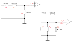
To avoid possible (further) confusion, this little picture now shows that I use the blue nomenclature in my spreadsheet. R1 is the termination of the system. Rq (i.e. a purely resistive replacement component) is not used here, the SSheet is not the win32 program noise.exe.

Marcel, you know that for the compensating and compensated input currents, only the oppositely directed DC components are subtracted, while the uncorrelated noise is always RMS added. With perfect symmetry, the DC currents are reduced to zero, while the noise is increased by a factor of 1.41 or 3 dB.
I think it is generally rather worse than that. For example, see Base Current Compensation Example in https://audioxpress.com/article/boo...spice-models-to-simulate-vintage-op-amp-noise for my analysis of the noise of the LT1028/LT1128 base current compensation.
The OP27 only has a tail current ratio of 2 rather than 6, so the ratio between common-mode and differential noise current will not be as bad as for the LT1028. I didn't bother calculating the value.
Well I'll confess its an over-slmplification, I think the noise from Rl isn't represented and its about 0.6pA/√Hz as a current for 47k, into a low impedance.View attachment 1441834
Do you think Mark's algorithm is correct? Please take a detailed look at the source code.
HBt.
Psst.
I don't work with Python, but I regularly have to be able to read sources from students.
The correct calculations consider each resistive noise source separately and figure out its contribution at each node in the circuit as either a Thevenin or Norton source, then use superposition to combine them all at nodes you are interested in (which for noise is calculated using root-sum-squared for separate, uncorrelated noise sources). Its a bit more cumbersome - LTSpice can do the work for you...
The code is doing the standard 3-part calculation, device voltage noise Vn_V, device current noise reflected into the input impedance Vn_I, and source resistance noise Vn_Rs. Since these are uncorrelated they root-sum-square to the result
- Home
- Source & Line
- Analogue Source
- Quick comparison -> OP-Amp Noise -> Simplified calculation