You tell them, Mile !!
I have lost interest in this forum because of all the squabbling over "simulated" topologies, dissing over actual working submitted designs, etc.
I had pondered over the years about submitting one of my guitar amplifier designs, based on IRF610/IRF9610 driving TIP142/TIP147, than decided "ah, the h*ll with it; don't need to defend myself against the trolls".
Hi
Sorry but it is not good to tell beginners that a circuit which does not have current sharing resistors in the emitters of parallel transistors is good practice. In post 87 there is an example of how this might be done (only the general idea - there are several errors in that circuit too {e.g. too high voltage for the 2N3055H, wrong short circuit protection connections}). Post 228 shows collector resistors which do absolutely nothing in three of the output transistors. That's not good guidance for beginners.
To show that I do not always criticise, let's consider crossover distortion. I agree that the circuit is basically the right architecture (not a criticism!). Anyone who has a Miller stabilised amp may like to compare the distortion with output-to-VAS connection and sprog stoppers. It will probably be 10 times better. Ed Cherry used this trick in his NDFL circuits in the early 80's, which probably helped to get ppm levels of distortion.
Unfortunately the large capacitors used (470pF) will limit the audio response anyway. A very good beginners amp could have been proposed with this circuit using 2N3055 outputs (50-60W from +/- 35V rails) which would have only needed say 100pF sprog stoppers (possibly 220pF) but smaller Miller capacitor to give a better frequency response. I've measured almost the same crossover performance (thd .01% at 10 kHz) for a quasi compared with a fully complementary using this concept.
FOr good symmetry, I would recommend two sets of resistors in parallelled output (lower half) transistors. One in each emitter, but the others in the collectors can be parallelled to give the same overall resistance. THe PNP driver emitter can be connected to this parallel junction or through a Baxandall diode. I did not measure much improvement when using a Baxandall diode does not make much difference when the output-to-VAS compensation is used, but it is marginally better.
John
Hi
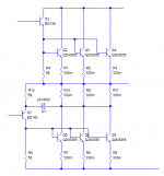
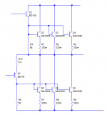
Here are two ways to parallel a quasi output stage. The first is probably the better approach but has an additional set of power resistors. The second is cheaper but care has to be taken to make sure that the voltage drop across the resistor of the pnp driver does not become excessive.
John
Here are two ways to parallel a quasi output stage. The first is probably the better approach but has an additional set of power resistors. The second is cheaper but care has to be taken to make sure that the voltage drop across the resistor of the pnp driver does not become excessive.
John
Attachments
Hi.Mr.Mile..can B500 redesign with quasy complementary on final transistor?
If yes..I will try it..
Pozdrav
If yes..I will try it..
Pozdrav
It is quasi, do you mean complementary?
In the Quasi it may be helpful to use an extra bias diode and add the Baxendall diode (#363a)
In the Quasi it may be helpful to use an extra bias diode and add the Baxendall diode (#363a)
Thanks djk...
Yes I mean quasy complementary. I will try on Apex B500 (full complementary) in another thread..Sorry my english..
Regards
Yes I mean quasy complementary. I will try on Apex B500 (full complementary) in another thread..Sorry my english..
Regards
Hi.Mr.Mile..can B500 redesign with quasy complementary on final transistor?
If yes..I will try it..
Pozdrav
No, this amp is completly different from B500. Feedback and compensated for work in class B, simple and without any adjusts. No perfect sound like B500.
It is quasi, do you mean complementary?
In the Quasi it may be helpful to use an extra bias diode and add the Baxendall diode (#363a)
No need for class B.
No, this amp is completly different from B500. Feedback and compensated for work in class B, simple and without any adjusts. No perfect sound like B500.
Thanks Apex..I know that..I can't modified Apex B500 with quasy complementary because different topology..
Pozdrav..
Hello,
Hi Mile, Which would be a more better sub amp, quasi or class d.
I have a 12" sub which can handle 300 watts rms. Can you suggest a good amp for this purpose.
Hi Mile, Which would be a more better sub amp, quasi or class d.
I have a 12" sub which can handle 300 watts rms. Can you suggest a good amp for this purpose.
Hello,
Hi Mile, Which would be a more better sub amp, quasi or class d.
I have a 12" sub which can handle 300 watts rms. Can you suggest a good amp for this purpose.
Use quasi, and with more expirience go to class D.
![SDC10332 [1600x1200].JPG](/community/data/attachments/193/193668-728033a518ecd0828d54a2659382497c.jpg?hash=coAzpRjs0I)
hi apex, its your quasi, semi assembled.
Nice, I suggest to use some protection...
sorry mr apex want to ask how much lay out the size of the post ..... apex? ask permission if I may be allowed to make and I wear?
Hi kkantzz
The emitter resistors probably need to be increased. IF you have three transistors with 0.33 ohms each, the total emitter resistance is effectively 0.11 ohms. This is usually not enough to be certain that the currents are stabilised. The overall resistance could be 0.33 ohms, so each individual resistor could be 1 ohm and the currents should be distributed better.
THis also depends on the heatsink you are using, and for high power amps I normally use very low thermal resistance heatsinks which would be OK with lower resistor values.
Next time your amp is powered up check the voltage across each resistor. The
Hi kkantzz
The emitter resistors probably need to be increased. IF you have three transistors with 0.33 ohms each, the total emitter resistance is effectively 0.11 ohms. This is usually not enough to be certain that the currents are stabilised. The overall resistance could be 0.33 ohms, so each individual resistor could be 1 ohm and the currents should be distributed better.
THis also depends on the heatsink you are using, and for high power amps I normally use very low thermal resistance heatsinks which would be OK with lower resistor values.
Next time your amp is powered up check the voltage across each resistor. The voltages should reflect the quiescent current (e.g. 50 mA => 16 mV). If they are unequal, use bigger resistors or check if the transistors are all at the same temperature (mind any high voltages around). If the voltage is much higher then fitting larger emitter resistors will bring the current down as well as even out.
John
PCB size: 110x105mm
Request permission to mr mile, if allowed I will multiply the PCB Apex B class is for people in my own forum Indonesia??
thanks
- Home
- Amplifiers
- Solid State
- QUASI Amplifier for Beginners