Tried it on the amp again, with an 8 ohm load, and twisted the in/out BNC cables as well as the red/black clamp inputs of the QA190. The low end nonsense went away.
Will provide a screenshot, later as the amp warms up/stabilizes.
Will provide a screenshot, later as the amp warms up/stabilizes.
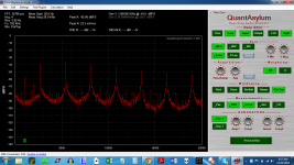
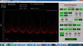
Here are the results, 8 ohm purely resistive load ( 3 resistors soldered together ) -14dB input, verified as producing 2.73 volts output. QA190 set to /10.
Looks like a resistor ladder is the only solution -- or the batteries are too low.
Will try brand new ones and build a ladder.
Or this is *really happening* -- which you'd expect to hear, as the noise is above the fundamental.
Looks like a resistor ladder is the only solution -- or the batteries are too low.
Will try brand new ones and build a ladder.
Or this is *really happening* -- which you'd expect to hear, as the noise is above the fundamental.
Attachments

There seems to be about 30mV dc from USB port ground (laptop) to QA190 ground. Nothing from amp to QA190 and 30 mV from amp to laptop. Forgot to measure QA400 to laptop.
No AC anywhere.
The amp sounds fantastic, I just can't measure it. Which is the whole point of getting the QA400.
Will try a 1K/10 ohm divider in parallel with the 8 ohm load (currently just 5W resistors) and alligator clip to BNC connectors later.
No AC anywhere.
The amp sounds fantastic, I just can't measure it. Which is the whole point of getting the QA400.
Will try a 1K/10 ohm divider in parallel with the 8 ohm load (currently just 5W resistors) and alligator clip to BNC connectors later.
Here are some quick images to help you along the way.
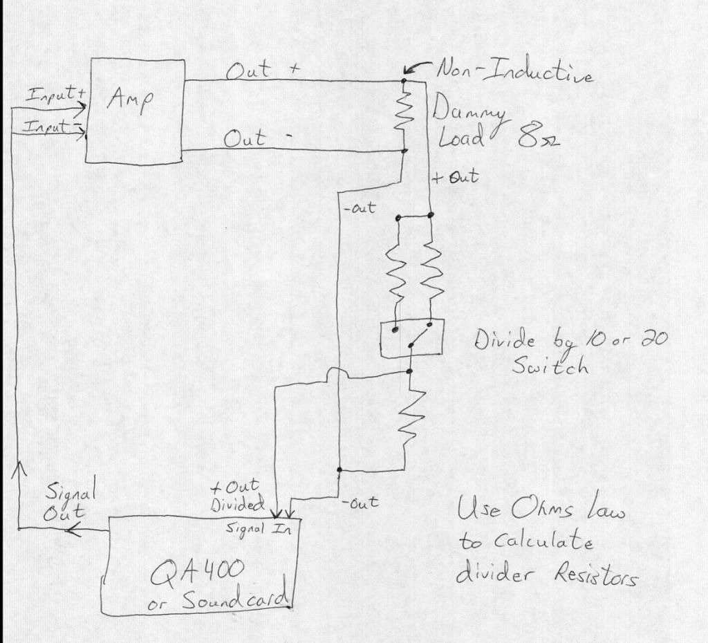
First, you need a divider. This is a simple sketch of a basic divider. Many have built similar and more elaborate (including over-voltage protection). Use Ohms law to figure out your divider ratios. I like to do mine in volts and not dB. I used divide by 10 and 20 as an example. You will need to figure out the base resistor that works best with the QA400. Others can chime in; I don't have a QA400. Again, this is a simple sketch to help you understand. Mine is much different than this, but all in all works great with low and high power amplifiers.
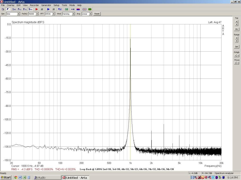
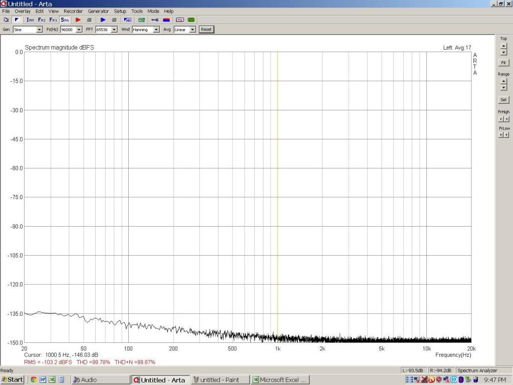
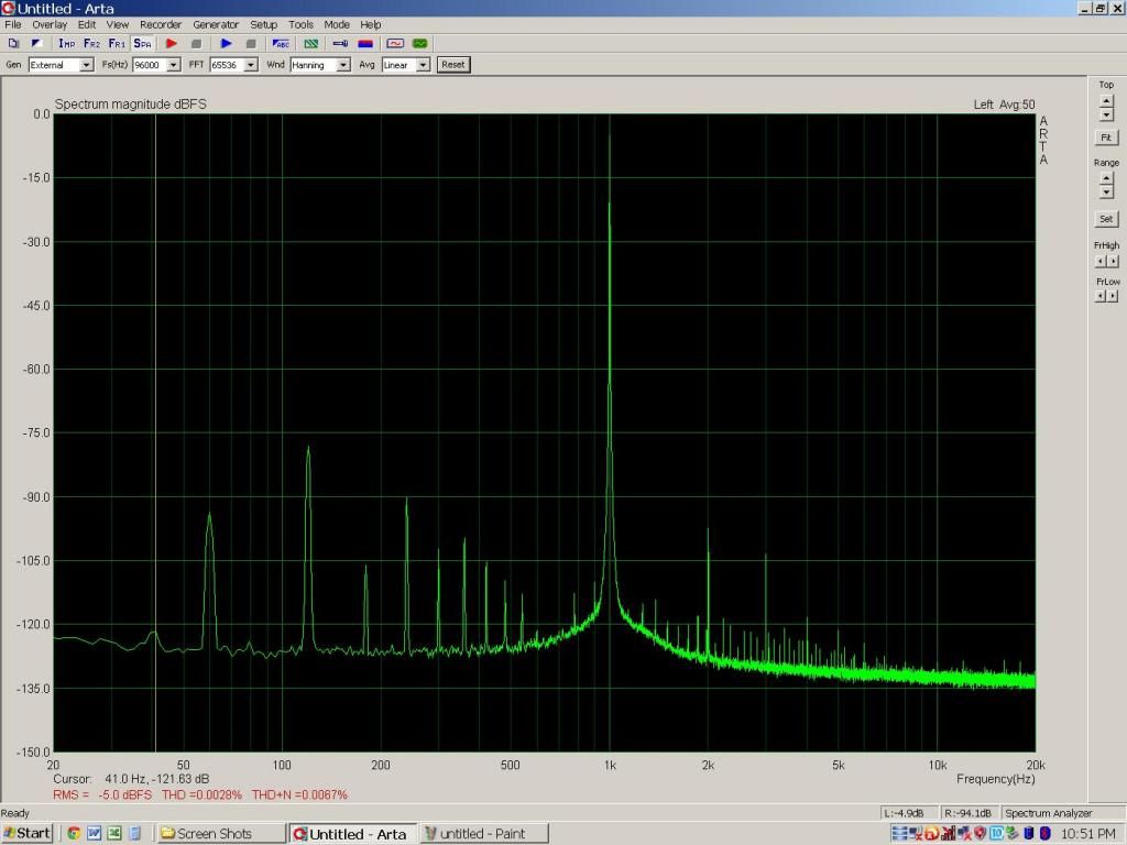
Here are some shots using ARTA and a sound card. Use these for reference purposes.
Loop back:
No signal:
Here is a solid state power amp at 10 watts:
Hope this helps.
First, you need a divider. This is a simple sketch of a basic divider. Many have built similar and more elaborate (including over-voltage protection). Use Ohms law to figure out your divider ratios. I like to do mine in volts and not dB. I used divide by 10 and 20 as an example. You will need to figure out the base resistor that works best with the QA400. Others can chime in; I don't have a QA400. Again, this is a simple sketch to help you understand. Mine is much different than this, but all in all works great with low and high power amplifiers.

Here are some shots using ARTA and a sound card. Use these for reference purposes.
Loop back:

No signal:

Here is a solid state power amp at 10 watts:

Hope this helps.
What Skidave said.
That's a drawing of what I said earlier.
You can skip the switch, just calculate the divider.
1audio said to use a 100k/1k voltage divider to start - close enough.
For a one time setup you can just put the 100k/1k across the 8 ohm resistor and connect the QA to the amp ground and the center point of the divider - the 1kohm goes to the GROUND side.
You only need one input to the amp. Unless it is a balanced input amp, and the F5 is not. Assuming you test one channel at a time.
Skip the differential box for now. Get the QA400 measuring correctly first.
Keep it simple.
No twisting of anything required. First get something like a reasonable looking display. Like one of those shown. It can be imperfect, but you ought to have big tall spike for the fundamental and harmonics much lower down.
_-_-bear
PS. be certain to use at least an avg setting of >6...
Last edited:
Good Job Ski, Bear, David, Demian, BigE.
Ski, thanks for the hand made drawing.
It seems it's easier to hand draw and pic
it or scan it than is it to fool with a drawing
package.
Now I know how to hook up an amp and go.
I think, at least until I try it.
Ski, thanks for the hand made drawing.
It seems it's easier to hand draw and pic
it or scan it than is it to fool with a drawing
package.
Now I know how to hook up an amp and go.
I think, at least until I try it.
Here are some quick images to help you along the way.
First, you need a divider. This is a simple sketch of a basic divider. Many have built similar and more elaborate (including over-voltage protection). Use Ohms law to figure out your divider ratios. I like to do mine in volts and not dB. I used divide by 10 and 20 as an example. You will need to figure out the base resistor that works best with the QA400. Others can chime in; I don't have a QA400. Again, this is a simple sketch to help you understand. Mine is much different than this, but all in all works great with low and high power amplifiers.
Hope this helps.
Yup, that was what I was going to make with 1audio's 1K/10R divider.
But the load must be *non-inductive*. The 8 ohm I have measures at 125 uH, the leads measure 15 uH. Will this cement resistor do?
Does the resistor ladder also have to be non-inductive?
Measuring at 1KHz the inductance won't be a big issue. The phase shift and reduced power won't completely invalidate your measurement. You could caculate the effective Z of your load at the test frequency. The divider resistors if they are 1/4 w will not have any significant reactance at audio frequencies.
I used 10 watt resistors for the divider. Here is what I got, delivering -14 dB.
First test is 1KHz, next is 4KHz. Going to swap out the cheap aux circuit transformer for a potted toroid.
Next will be a repeat of these measurements.
First test is 1KHz, next is 4KHz. Going to swap out the cheap aux circuit transformer for a potted toroid.
Next will be a repeat of these measurements.
Attachments

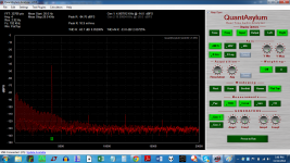

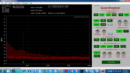
So what is going on? Same setup, perhaps the contact from BNC to RCA was poor so that the value of the fundamental could change so much??
Still not happy with the boatload of harmonics. Will try Quasimodo, but then, may have to rewire the amp.
Still not happy with the boatload of harmonics. Will try Quasimodo, but then, may have to rewire the amp.
Last edited:
When you say -14dB what do you mean? Do you mean the amp output voltage is -14 dBV (200 mV??)? Or the signal into the amp is -14 dBV? The input to the QA400 seems to be about 10 mV. Are you using the -40 dB attenuator (1K/10 Ohms) I suggested? The signals are really close to the noise floor and if the output of the amp is under 1V you can connect directly. Just be really careful.
I'm confused about the reference to a transformer or toroid -- what do these have to do with what you're doing? The amount of hum signal is unreasonably high -- if you are transformer coupling the measurement gear, that could be why. Or if you are measuring with a current sensing transformer, well, then don't do that.
I believe that he is referring to the power transformer. I'm familiar with the amp he is testing.
So, are you using BNC cable s with RCA adapters? It looks like your signal cables are not shielded or you are just using individual wire.
Recommendation; loop back your QA400 and get a good reference with your 1KHz signal. Then connect your amp and input a small signal, say .150 volts. Measure the input w/ a volt meter if you are unsure. See what your output voltage is. Connect to your divider if needed and feed it into the QA400. Increase your input and see when your amp starts to increase distortion. Do not do more than one change at a time.
You will not be able to see the difference between transformers until you get clean fft responses.
Ummm... dear BigE, what are you doing??
If you followed what skidave put down on his drawing, you would not likely have results that look like that... also you've got the bottom axis not set up so that you can see it clearly... think you want to switch the preferences/options for linear vs. log on that axis??
What I'm not seeing is the expected 2nd & 3rd harmonic, so somehow I doubt that we are seeing the output of an F5 amplifier... even with the odd noise that is showing up...
how about a jpeg of the set up?
BigE you are testing without the differential box?? It's important to not use the differential box at this point.
_-_-bear
Last edited:
I will answer the questions and then I must be off for a while. I have a family member with a health crisis flying in an arriving in about an hour. I will be attending to her shortly.
-14dB is the same as what gets sent out from the "settings/generate fixed tone" menu. I set that to 60 Hz and -14. The output of the amp is 2.77 VAC when the tone is applied. The 1K - 10R series resistor network is in parallel with the 8 ohm load. What you see on the graphs is taken across the 10R resistor using a BNC to alligator clip connector. The input to the amp is provided with a BNC cable with an RCA adapter.
The toroid refers to the new transformer for the auxiliary circuits ( speaker protection and the 555 timers/relays that make up the slow charge circuit). This 12VDC power is created with a 7812 regulator. I thought perhaps the cheap EI I was using was the cause of the noise. It was not.
I will get a photo of the setup out when I get a chance. Possibly tomorrow or the next day. I envision seeing the sunrise at the hospital.
Wish her luck tonight...
Focus on what is important. The amplifier will still be there.
to follow what you are saying-
1) Input to amp is 200 mV
2) Output from amp is 2.77V (24 dB?)
3) You are using the 40 dB divider I suggested so the input to the QA400 with 2.77V should be 27.7 mV. Low but not so low you cant get useful info.
4) The hum is present in all the measurements. when the amp is connected.
Here is what I would be doing next-
1) increase the drive to 1V, which should get you 13.5V out. The divider will 135 mV at the input of the QA400
2) The hum will still be there but the signal to noise ratio will have improved.
3) Disconnect the input of the amp from the QA400 and short it at the connector.
5) if the hum reduced its something on the input side, probably some ground current or oscillation internal to the amp. if oscillation it will be ultrasonic so you won't see it on the QA400 or hear it.
6) if the hum is still there switch off the amp with everything still connected. Did the hum go away?
7) If yes then disconnect the secondary of the power transformer to the rectifiers and switch it back on. The transformer will be the only element with power. if it's radiating a hum field and is getting picked up you will see it now.
When everything returns to normal (a few days I suspect) try these steps, take a picture and let us know what you find. It may well be oscillating with the input and output connections both going back to the QA400. A quick test would be to disconnect the ground side connection between the divider and the input of the QA400. The ground from the source side is all you actually need to get a good signal.
Hi,
I will be receiving a QA400 and a used Pete Millet sound interface in the next couple of weeks, and want to prepare some cables to connect them together.
As the QA400 use BNC connector and the P.Millet interface use 6.3mm phone jacks for the soundcard in/out, I'm going to make a few short BNC to 6.3mm phone jack cables. To get best noise performance, would it be better to use standard RG-58A coaxial cable (crimp the BNC connector at one end, solder the core/shield to the phone jack at the other end), or I would be better off using a shielded twisted pair (solder the cable to a phone jack at one end, and a RCA connector at the other end, which connects to a RCA->BNC adapter - cause I am unable to find BNC connector which is directly solderable).
In case shielded twisted pair is to be used, how should I connect the shield (floating, or connect to signal ground in one end, or both ends)?
Thanks and regards.
Last edited:
- Home
- Design & Build
- Equipment & Tools
- QuantAsylum QA400 and QA401