I will answer the questions and then I must be off for a while. I have a family member with a health crisis flying in an arriving in about an hour. I will be attending to her shortly.
-14dB is the same as what gets sent out from the "settings/generate fixed tone" menu. I set that to 60 Hz and -14.
Wish her luck tonight...
Hope your family member comes through fine.
Why not set the frequency to something more usable, like 1kHz??
Then a bit more drive to the amp, per Demian's suggestions...
_-_-
Hi,
I will be receiving a QA400 and a used Pete Millet sound interface in the next couple of weeks, and want to prepare some cables to connect them together.
As the QA400 use BNC connector and the P.Millet interface use 6.3mm phone jacks for the soundcard in/out, I'm going to make a few short BNC to 6.3mm phone jack cables. To get best noise performance, would it be better to use standard RG-58A coaxial cable (crimp the BNC connector at one end, solder the core/shield to the phone jack at the other end), or I would be better off using a shielded twisted pair (solder the cable to a phone jack at one end, and a RCA connector at the other end, which connects to a RCA->BNC adapter - cause I am unable to find BNC connector which is directly solderable).
In case shielded twisted pair is to be used, how should I connect the shield (floating, or connect to signal ground in one end, or both ends)?
Thanks and regards.
Whatever is easiest for you to assemble. If you use the twisted pair connect the shield at both ends. Twisted pair only works with balanced differential signals. Your signal is unbalanced.
Hope your family member comes through fine.
Why not set the frequency to something more usable, like 1kHz??
Then a bit more drive to the amp, per Demian's suggestions...
_-_-
Thanks. she's home from surgery, healing, but there were complications. results are noy perfect, but she will be healthy.
The 60 hz is so that the meter can read it. it does not affect the test frequency.
The concern is that two different tests show different values of the fundamental. I will put a different setup together, using a banana to bnc connector.
Also, will work on shorting the input to locate the source of noise. That is a good idea. I am sure there are several sources. I have ordered some inductors to convert to CLC. Also am awaiting the replacement scope to arrive, to check ps.
BigE, are you concerned about hum being produced by the amp, appearing in the electrical ouput?
I'd ignore this aspect for now.
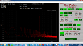
For now, get a few watts of power out, get the fundamental at 1kHz., get that fundamental to about -10dB on the QA display, and show the FFT results - you should be seeing the fundamental and the 2nd and 3rd harmonic down 20-40dB below the fundamental (or more).
Until you see this, don't do anything else to change the amp.
I'd ignore this aspect for now.
For now, get a few watts of power out, get the fundamental at 1kHz., get that fundamental to about -10dB on the QA display, and show the FFT results - you should be seeing the fundamental and the 2nd and 3rd harmonic down 20-40dB below the fundamental (or more).
Until you see this, don't do anything else to change the amp.
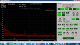
OK, so I reworked the resistor ladder, and built it on a banana to BNC connector. The input was removed, but not shorted on the final test. All tests are still at -14 dB.
It is looking a lot better, but the nasty PS stuff is still there... maybe feedback from the BNC cable?
I ordered some pomona, with additional shielding. The will arrive Monday.
I am happy to see that the 2nd harmonic is above the 3rd.
It is looking a lot better, but the nasty PS stuff is still there... maybe feedback from the BNC cable?
I ordered some pomona, with additional shielding. The will arrive Monday.
I am happy to see that the 2nd harmonic is above the 3rd.
Attachments

Last edited:
Thanks....Whatever is easiest for you to assemble...
Thanks for the great article, took me 2 hours to read it but now I understand a lot better.Pin 1? -- read this from Rane: Grounding and Shielding Audio Devices
OK, so I reworked the resistor ladder, and built it on a banana to BNC connector. The input was removed, but not shorted on the final test. All tests are still at -14 dB.
Why are you still at -14db??
Turn the generator level up?
Why are you still at 4 avg?
It is looking a lot better, but the nasty PS stuff is still there... maybe feedback from the BNC cable?
Does it change when you move the BNC cable around?
Move the QA around?
If it changes then you are picking up something.
If it stays the same, then it is likely coming out of the amp.
Does the hum looking harmonics change level when you change the level of the drive signal?? This is an important test.
Is this a stereo amp with a single supply?
If so, drive one channel (dummy load) and measure the second channel. It might show the hum alone.
Also make sure that when you are driving the channel under test, that there is NOTHING coming out of the "unused" channel. If it is oscillating, that will draw a boatload of current and cause a whole lot of PS ripple.
Keep in mind that the hum looks like it is down -90db below "0"... and depending on where you are WRT to full power of the amp, this may be within spec.
I ordered some pomona, with additional shielding. The will arrive Monday.
I am happy to see that the 2nd harmonic is above the 3rd.
Also, the F5 does not have a particularly great PSRR (power supply rejection ratio) so hum in the power supply rails will not be completely eliminated by the circuit itself...
Again it would be useful to see some images of your arrangement, there may be something obvious that you are overlooking, that nobody here can see.
Do you have a commercial amp or receiver you can test?
That would give an indication of what is going on...
+1 on what bear said about testing a commercial amp or receiver to gain a better understanding of how the QA400 operates and some good spectrum responses.
Did you ever hook this amp up to a speaker. Does your speaker hum loudly? It looks like it has 60 Hz hum dominating everything.
Did you ever hook this amp up to a speaker. Does your speaker hum loudly? It looks like it has 60 Hz hum dominating everything.
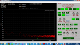
One more thought, is there an input connector issue? Meaning is the input ground to chassis ground, power supply ground, or not grounded at all. I'm think there is an issue with input signal ground based on the last image in post # 1426. The last image he says the input is not shorted - floating. There is no 60 Hz noise. When the QA400 is connected in the preceding photos, the 60 Hz noise is everywhere.
Indeed, this is why I am awaiting double shielded cables. I am suspecting some sort of stray radiation id being picked up and amplified.
Yes, I have run this amp through a full range speaker. There is no hum. I DO have an issue with the power supply of a BBC SP10 mkII humming loudly, and my TT does pick up some hum from that source. Oddly, only in the right channel.
I've misplaced my camera... I've been looking for it for a couple days now to get some shots of this setup. It will be uploaded when it comes.
Right now, the amp is being used in a tri-amp setup as the mid-bass from 340 to 700 Hz. An 18 inch is below and an altec 511b horn is above.
I think the amp is oscillating with the input and the output sharing a ground connection. Its a common problem with test setups and why usually the analyzer has a balanced input. What happens is some of the output return current is creating a voltage at the input. It usually takes very little to get some oscillation.
I suggested earlier only connecting the source to the input of the amp. Connect the divider to the output of the amp. Connect ONLY the divided point back to the input of the QA400. With a 1K-10 Ohm divider you do not need a shielded cable. The source impedance is way too low to pick up voltage.
I suggested earlier only connecting the source to the input of the amp. Connect the divider to the output of the amp. Connect ONLY the divided point back to the input of the QA400. With a 1K-10 Ohm divider you do not need a shielded cable. The source impedance is way too low to pick up voltage.
Hum from TT seems fixed...The hash from the speaker was happening even with the DCX2496 muted, and it moved with the RCA input to the other channel. The output XLRs on the DCX2496 have some sort of grips on the outputs that need to be pushed down.
Skidave:
The input RCA shields are attached to the FE board, via twisted 20 AWG wire. The shield references safety ground via a ground loop breaker circuit for each FE board.
Funny, all this work to reproduce only a range of 360 Hz. Learning how to cross over an active system is also happening at the same time.
Still can't find the camera. Will post more charts on Monday, when the cables arrive. I want to discount any effect from the cables. These two cables cost half as much as the entire QA400.
I think the amp is oscillating with the input and the output sharing a ground connection. Its a common problem with test setups and why usually the analyzer has a balanced input. What happens is some of the output return current is creating a voltage at the input. It usually takes very little to get some oscillation.
I suggested earlier only connecting the source to the input of the amp. Connect the divider to the output of the amp. Connect ONLY the divided point back to the input of the QA400. With a 1K-10 Ohm divider you do not need a shielded cable. The source impedance is way too low to pick up voltage.
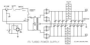
The input and output reference the case ground via a ground loop breaker. This is as per the F5T power supply schematic. They are joined on the same side of the ground loop breaker. The optional oscillation control caps are installed. There is a difference though, I have installed some larger caps on the F5T output boards, to act as PS bypass -- perhaps these are causing problems? However, if that were so, I would hear it through the 95 dB efficient speakers.
I will connect the divided point back: divided point to BNC center pin, speaker return to BNC shield and amp input BNC/RCA connector removed from QA400 side but still connected to amp and report that tomorrow.
Last edited:
You probably won't hear the ground issues with speakers since the low side of the speaker never connects to the input ground. If there is impedance between the ground node of the input of the amp, the point where the feedback returns to, as the low side of the input cable you will have problems. I find the best practice is to either build the amp so it can be "double insulated" or connect the internal circuitry to the chassis at one point through a 10 Ohm resistor. Grounding cables to a chassis and then to a building safety ground usually leads to noise problems. You can use a GFCI and leave off the ground and actually have a safer setup.
I will connect the divided point back: divided point to BNC center pin, speaker return to BNC shield and amp input BNC/RCA connector removed from QA400 side but still connected to amp and report that tomorrow.
Do connect the shield from the amp in connector through the BNC shield. Don't even connect the speaker return to the shield. Leave the shield to the BNC connector on the QA400 intact. You could even add a 100 Ohm resistor in series from the divider to further isolate the amp from the QA400. The electrostatic shield would come from the connection to the amp input. You want the shielding to be at the most sensitive point in the chain, which is the amp input. The output is the least sensitive since its very low impedance.
Do connect the shield from the amp in connector through the BNC shield. Don't even connect the speaker return to the shield.
Do I have this right?
On the amp input: business as usual.
On the amp output: using a BNC to alligator clip cable, attach the red clip to the 1K/10R junction, but do not attach the black clip to the speaker return binding post/1K junction.
You probably won't hear the ground issues with speakers since the low side of the speaker never connects to the input ground. If there is impedance between the ground node of the input of the amp, the point where the feedback returns to, as the low side of the input cable you will have problems. I find the best practice is to either build the amp so it can be "double insulated" or connect the internal circuitry to the chassis at one point through a 10 Ohm resistor. Grounding cables to a chassis and then to a building safety ground usually leads to noise problems. You can use a GFCI and leave off the ground and actually have a safer setup.
The ground loop breaker I refer to is a diode bridge with a CL60 taking place of the resistor, like in the lower left of the attached pic. The ground symbol attached to the diode is the ground point for the power supply zero volt line, which is connected to the input RCA shield and the speaker return.
Attachments
Last edited:
Do I have this right?
On the amp input: business as usual.
On the amp output: using a BNC to alligator clip cable, attach the red clip to the 1K/10R junction, but do not attach the black clip to the speaker return binding post/1K junction.
Yes.
- Home
- Design & Build
- Equipment & Tools
- QuantAsylum QA400 and QA401