Sorry davada, I'm struggling with understanding this for some reason. It should be simple.
I will try to do something more sensible. The next post will be clearer, and hopefully without error. Anything that resembles a loopback works perfectly... eg DCB1.
There is much noise down low, around 60,180,300 420 etc... regardless of whether I run loopback or through and amp or preamp.
Thanks for your help, and I hope to not wear out your patience.
Truthfully, I would prefer to use the QA190 than a resistor ladder.
Why don't get it going with a good wire wound pot to start with and then get it going with a fixed attenuator. Once that is working then try the QA190 again. The pot can be 20k or 10k.
Do you have a multimeter or other AC meter to check the input signal to the QA400?
Do show us the control panel.
I'm really confused. We all need more details about what you are doing and what we are seeing.
First the amp you are testing, how much gain? Are you looking for open circuit performance or under load?
What is the output voltage of the amp you are testing?
Using some simple numbers here- amp w/ 26 dB of gain (20X) would nean that a 500 mV RMS output (-6 dBV) would be 10V RMS at the output. That divided by my X100 probe suggestion would give 100 mV across the 10 Ohm resistor. 100 mV is right in the optimum range of the QA400 and 1K should not load a power amp significantly. Your 33 Ohm/ 10 Ohm combo has the potential of frying the input of the QA400 and the resistors themselves. It works out to 2W in the divider resistors. (They can generate distortion themselves at that power level). Its also 2.5V RMS which is enough to cause problems and possibly damage the QA400.
I think there is a considerable voltage potential between the amp chassis and the QA400 chassis. With no probe attached measure the voltage between them. If its more that 24V STOP! Something is not right. it could be a line filter on the input of the amp. Most commercial line filters have 2 caps, one from the hot lead and one from the neutral lead tied to the ground/chassis. If you don't have a ground connection back to the main ground you will get 1/2 of the mains supply voltage on the chassis, 60V in North America. make sure it is grounded if you see the voltage. Then connect a 1K resistor between the chassis and the QA400 and measure the voltage across it. In both cases is should be small. I would expect no more that 50 mV with no other connection between the chassis and no more than 100 mV with the 1K resistor, which would be 100 uA of AC supply leakage current. If the laptop is on batteries and no charger attached it should be zero. This is actually how UL measures leakage current.
For what its worth a "probe" made of a 1K resistor (ideally 990 Ohms) and a 10 Ohm resistor will be so low impedance that you really do not need to worry about picking up noise or frequency compensation.
This kind of measurement is possible with the QA400.
This is a very low distortion generator. The fundamental is attenuated with a active twin t notch filter. I'm giving the input to the QA400 20dB of gain and set the extra gain in the QA400 to 20 dBV to scale the display.
This is a very low distortion generator. The fundamental is attenuated with a active twin t notch filter. I'm giving the input to the QA400 20dB of gain and set the extra gain in the QA400 to 20 dBV to scale the display.
Attachments
Ummm...
BigE, I'd put an 8 ohm power resistor (in this case >~30 watts) across the output of the amp. The divider network for your probe should now go across that resistor, so that the QA "hot" lead goes to the middle point of the divider and the ground shares the ground with the amp. The smaller resistor should go to the ground terminal + 8 ohm resistor on the amp. Presumably you have this set up already.
Hopefully ur using shielded cable for the QA.
I find that in my case the QA picks up a fair amount of LF stuff which shifts levels merely by moving the cables and the QA. I tend to ignore the LF side, and will until I figure out how to get it quiet.
Now when ur testing, you might want to use a scope to watch how much signal is coming out of the amp. Then adjust the gain on the input channel for the QA and/or the osc output level (watch for clipping the amp) until the fundamental is about -10dB below the top (aka Full Scale or "FS"). Now run the test, you should see a strong spike of the fundamental hitting ~-10 and the noise down at the bottom and the harmonics sticking out...
Later on, you'll want to test the amp at specific power levels by watching the scope to see the voltage and converting that to power WRT the load Z.
Your plots look like ur picking up "other" stuff. Also the fundamental is too low.
Davada, how did you get the noise floor down that low and no LF pick up??
That looks amazing.
Faraday cage?
Last edited:
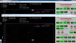
This is a McIntosh tube amp, a 50W-2, ought to have similar distortion characteristics to the F5 ur testing... FYI
(I think I was using an external osc which was not exactly precisely "in the bin" and that accounts for the shape of base of the fundamental, iirc)
(I think I was using an external osc which was not exactly precisely "in the bin" and that accounts for the shape of base of the fundamental, iirc)
Attachments

Thanks guys... I am going to be away until Sunday night. She who must be obeyed needs a dishwasher installed, and I have to pick up a pair of sub woofers.
Will respond later. THANK YOU.
Control panel shots will be forthcoming.
Will respond later. THANK YOU.
Control panel shots will be forthcoming.
I'm really confused. We all need more details about what you are doing and what we are seeing.
First the amp you are testing, how much gain? Are you looking for open circuit performance or under load?
What is the output voltage of the amp you are testing?
Using some simple numbers here- amp w/ 26 dB of gain (20X) would nean that a 500 mV RMS output (-6 dBV) would be 10V RMS at the output. That divided by my X100 probe suggestion would give 100 mV across the 10 Ohm resistor. 100 mV is right in the optimum range of the QA400 and 1K should not load a power amp significantly. Your 33 Ohm/ 10 Ohm combo has the potential of frying the input of the QA400 and the resistors themselves. It works out to 2W in the divider resistors. (They can generate distortion themselves at that power level). Its also 2.5V RMS which is enough to cause problems and possibly damage the QA400.
I think there is a considerable voltage potential between the amp chassis and the QA400 chassis. With no probe attached measure the voltage between them. If its more that 24V STOP! Something is not right. it could be a line filter on the input of the amp. Most commercial line filters have 2 caps, one from the hot lead and one from the neutral lead tied to the ground/chassis. If you don't have a ground connection back to the main ground you will get 1/2 of the mains supply voltage on the chassis, 60V in North America. make sure it is grounded if you see the voltage. Then connect a 1K resistor between the chassis and the QA400 and measure the voltage across it. In both cases is should be small. I would expect no more that 50 mV with no other connection between the chassis and no more than 100 mV with the 1K resistor, which would be 100 uA of AC supply leakage current. If the laptop is on batteries and no charger attached it should be zero. This is actually how UL measures leakage current.
For what its worth a "probe" made of a 1K resistor (ideally 990 Ohms) and a 10 Ohm resistor will be so low impedance that you really do not need to worry about picking up noise or frequency compensation.
Thanks. What part of the laptop should I take the measurement from? how about the screws for the vga conector?
You can leave the QA400 connected to the laptop via the USB cable and measure between the amp chassis and the QA400. If you want to test between the QA400 and laptop unplug the USB cable from the QA400 and measure between the USB casing and the QA400. USB cables are shielded and that casing is part of the ground.
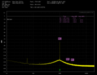
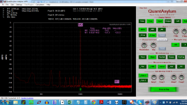
OK, so here is a loopback test. Is there anything funky going on here? I should be using Flat top I suppose. The laptop is plugged into the wall inh the first shot, and running on battery power second shot.
Attachments
Last edited:
You have a lot of hum in this loopback.
1) were you using a BNC to BNC cable?
2) try it with the laptop disconnected from power
3) use higher resolution to get a lower noise floor. I start with 16K.
4) What else is connected to USB on that computer?
5) Are there any large power transformers nearby?
The harmonics are very good. The hum spectrum points to a rectified power source since the second harmonic is the strongest. it could even be a power cord nearby radiatng that is supporting a large load like a monitor, an amp, a heater, an old scope ??.
OK, so here is a loopback test. Is there anything funky going on here? I should be using Flat top I suppose. The laptop is plugged into the wall.
You're getting a lot of mains pickup - surprisingly it's a little bit worse with battery than without.
Also, try adjusting the generator output for -9dBFS. That I find is the sweet spot for my QA400 in loopback.
One more thing - turn on averaging.

You have a lot of hum in this loopback.
1) were you using a BNC to BNC cable?
2) try it with the laptop disconnected from power
3) use higher resolution to get a lower noise floor. I start with 16K.
4) What else is connected to USB on that computer?
5) Are there any large power transformers nearby?
The harmonics are very good. The hum spectrum points to a rectified power source since the second harmonic is the strongest. it could even be a power cord nearby radiatng that is supporting a large load like a monitor, an amp, a heater, an old scope ??.
Yes BNC to BNC.
I editted the post to include the laptop on battery. Same....
What else is connected is a microsoft ergonomic keyboard/mouse.
I am in the basement of my house in Toronto. Our house is third from the transformer on the street.
There is an old scope but it is off. I will unplug it.
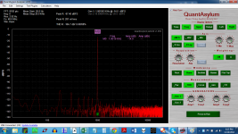
Below is a loopback that uses 12 samples averaged per point, and 32K samples for the FFT. The A/D was bumped up to 24/192 stereo.
Attachments
Last edited:
You have a lot of hum in this loopback.
1) were you using a BNC to BNC cable?
2) try it with the laptop disconnected from power
3) use higher resolution to get a lower noise floor. I start with 16K.
4) What else is connected to USB on that computer?
5) Are there any large power transformers nearby?
The harmonics are very good. The hum spectrum points to a rectified power source since the second harmonic is the strongest. it could even be a power cord nearby radiatng that is supporting a large load like a monitor, an amp, a heater, an old scope ??.
I had a problem with those screw in florescent lights once. It was raising the 2nd H on a 1kHz fundamental. Turned the light off and the problem went away. If coax cables are coiled up they act as a pickup for hum and rectified power.
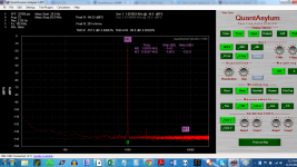
The averaging helps. Using the higher sample rate raises the noise floor and potentially the distortion. You have no distortion issues in this.
Do you have a big coil of wire available? You can connect it to the QA400 and use it as a search coil for the hum fields. I doubt you will find it any other way. It could even be a lamp ballast. I have similar issues and when I raise DUTs 10" above my bench hum will often go away. I really don't know the source of the field. I'm sure it will contribute to my insanity later. . . .
Do you have a big coil of wire available? You can connect it to the QA400 and use it as a search coil for the hum fields. I doubt you will find it any other way. It could even be a lamp ballast. I have similar issues and when I raise DUTs 10" above my bench hum will often go away. I really don't know the source of the field. I'm sure it will contribute to my insanity later. . . .
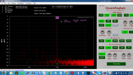
CHECK THIS OUT: I twisted the coax from input to output during the loopback test, and the harmonics vanished. The loop formed by the coax was acting like an antenna.
That's better.
the change from 0 averaging and 10 averaging makes a big diff, so hard to compare results... but it looks very good now - probably better than mine in terms of where the floor is...
- Home
- Design & Build
- Equipment & Tools
- QuantAsylum QA400 and QA401