I didn't know one can use a GFIC in place of an earth ground.
I wonder if CSA accepts that as well.
I wonder if CSA accepts that as well.
The fundamental level is too low to be useful -- get it up about 30 or 40dB. The mains noise is at a fairly low level now, with 60Hz at -90, so you've gotten some big improvement in S/N.
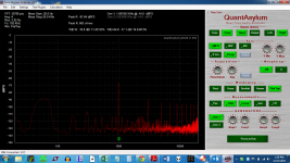
Please see the charts attached to post 1426. I see no significant gain in noise performance at 60 Hz at all. Worse yet, the 2nd order harmonic is now below the third. This is opposite to the measurements in 1426.
I am expecting double shielded BNC to arrive tomorrow or the next day.
I am expecting double shielded BNC to arrive tomorrow or the next day.
Last edited:
I'm a biot confused as to why you expect the 2nd H to be higher than the 3rd. Wh at does this mean to you?
The sound of this F5T is soft and lacks detail and punch. The F5 I have to compare is not soft, nor does it lack detail/punch. Conventional wisdom says *this* F5T has a higher 2nd order harmonic than 3rd, while the F5 has little 2nd order harmonic. I have made measurements of each amp that show this, albeit with the high noise floor. The charts on post 1426 corroborate this at least for the F5T.
This new chart does not. Why would the distortion now jump to 12% from the earlier 0.025%? Why would the distortion components just not be stuffed into the grass? I assure you that the amp does not sound like 12% distortion. I do not trust this new measurement. Bear in mind, this is all with the same output level. Why would the input level of the fundamental drop, while the harmonics rise?
The whole point to this exercise is to adjust a pot in the F5T to tailor the relative levels of H3 and H2.
And to top it off, there is no lowered noise floor. It's still over 90 dB.
I can try raising the output, but why did this measurement not show the same harmonic structure are the others?
Last edited:
Oooooookay -- so higher distortion gives the sound you like.... De gustibus non est disputatum. (that might be lousy Latin -- it wasn't my best subject)
Although the noise level is at -90, that's not terrible -- the actual signal-to-noise ratio is a lot higher because you have to add back in the attenuation of your output divider, which is significant.
Now you have to adjust the divider ratio and/or the output level of the amp to boost the fundamental signal into useful territory -- between -20 and 0dB. As you do that, the harmonic ratios may change and so might the calculated values. The software analyzer needs sufficient signal to do its work.
I don't know what you are trying to infer, but I prefer the sound of the F5, as it is not soft and dull. It happens to have less distortion than the F5T. With the shoddy measurements I am making, the F5 measures at less than half the distortion of the F5T.
I have seen this noise on the loopback tests, which went away when I twisted the BNC cables together. There was NO evidence at all of 60 Hz or it's harmonics. This led me to believe that the cables need better shielding, so I bought better cables, which have not yet arrived.
The amp has a gain of 23 dB. This was measured with a 60 Hz tone and a True RMS meter. According to the math, for -14db out, I should expect to see about 2.83 V out. I measure 2.77. With this divider, we should see 0.0277 at the output or -15.68 dB. It is far off that.
I shall replace the 10 ohm with 100 ohm, and not touch the -14dB input. It is important to leave that alone, as with that input, the amp provides 1 watt output, which is where the THD measurements are made.
It is important to leave that alone, as with that input, the amp provides 1 watt output, which is where the THD measurements are made.
Who's standard is that?
Sounds like a recipe for huge amounts of crossover distortion a high levels.
@BigE -- not meant to infer a criticism; just a lot of experience with amps and their owners. Sorry, it's actually not about you.
Now, as to levels -- you should shoot for an input to the QA400 of about 600mVRMS at 1kHz, according to the local lore around here, as that apparently gives the QA400 its own best distortion performance while preserving adequate dynamic range.
So, if you want your amp to be measured at 1W into 8 ohms(?) then you want 2.83VRMS output from the amp across your 8 ohm load. BTW, is this amp a Class A amp? I ask because I'm not familiar with it.
I personally would give my divider an attenuation of about 12dB, but I would put a 100ohm pot as the bottom leg of the divider so that I could easily set my amp output level, then dial in the best input level to the QA400, which will be at around the -6dB level on the plot; but using -10dB as the ref level makes all the math easier.
I think that there are real grounding issues with the output of the amp, and that your intent to use the QA190 diff probe was a well-founded one. Since I don't have one, I can't comment on using it, but you're not getting the signal level you want in part because the ground reference is not right at the amp output. This is the kind of measurement hassle that results from using a signal generator and analyzer that share a common ground, and is why HP and Sound Tech and many others use balanced inputs and/or outputs on distortion analyzers.
I know the advice to not use the QA190 was well-intentioned, but I think that it is exactly what you need. I also am of the opionion that you are measuring in the middle of substantial magnetic interference (EMI) and that dealing with that is really a difficult issue, because ground loops are nearly inevitable.
Hang in there -- you are making progress. And everyone here is also ready to help.
Thanks richiem, I am just having a lousy lousy day. I should not poke at others. I apologize for that.
I will calculate the resistor ladder to yield the 600 mv to the device. I wish I could find my camera. I bought it just to take these shots
FYI, the F5T is the Nelson Pass F5 Turbo. It is a version with more output pairs and higher voltage rails. My amp delivers about 75 watts RMS class A into 8 ohms. It was built to power a pair of 4 ohm speakers that are full rangers -- all the way to 20 Hz. It was also built to use up a transformer that I had lying around. As it happens, I've learned a lot in the process.
The amp should not be causing this sort of oscillation. If there is any oscillation, it would be present because of non-snubbed diodes in the power supply, but I used soft-recovery diodes which are not supposed to trigger transformer ringing. And even if it did, it would be at a much higher frequency.
I too am of the opinion that the noise levels are from EMI interference. Even the loopback test has them, and they do vanish when the loop is twisted.
According to my calculations, the 10 ohm resistor ought to be replaced with a 260 ohm resistor. This would create a voltage drop of nearly 0.6 volts RMS. This would be of minimal power.
OK, so off to the bench!
And thanks for the help. I do appreciate it.
So this thing has a massive power transformer and huge filter caps and draws tons of standing current -- this is a measurement nightmare, for sure. The double shielded cables may help. I have no idea what the nominal distortion performance is supposed to be, but I imagine it might be in the 0.1 to 0.01% area at 1W into 8 ohms -- this means the QA400 should show harmonic spikes below -60dB, maybe even below -80dB. If the amp is substantially better, then the distortion might be nearer the noise floor.
For the sake of argument, if the divider attenuation for the QA400 is 12dB, and the noise floor of the r4esulting plot is -90dB, then the 1W S/N will around -102dB, which for an amp of this kind would be very good. Remember that what you see on-screen in the plot is hard to reconcile with the calculated results, because the noise and signal components sum as the root of the mean square -- RMS. In general, I find the the individual spike peaks will often be 10dB lower than the computer totals.
As to oscillation, the only way to check that is with a wide-band scope -- say 50MHz or more, with relatively high sensitivity -- I use a Tektronix 7603 with a 7A13 (or 7A26 or 7A22, depending on requirements). The 7A13 has differential inputs which would let you look at the amp output without concern for ground scheme.
Oh dear.
First step. Do whatever you need to do in order to get the fundamental in the -10dB range on the display. Increase the gain on the soft knob of the QA or increase the generator level. Then look at what you have.
Next step set the output level to your proscribed 2.83v into 8 ohms and adjust the divider values so that this produces the required ~-10dB on the QA screen.
Use a scope or DVM to get the resistor values close.
The F5 is a pure class A amplifier.
The F5T is a similar amp but with a cascode at the input so that it can be run with higher PS voltage. I think that one also has Nelson Pass' "magic diode" across the resistor that is in series with the output Mosfet(s).
Among the causes of differences in sound from the F5 (never mind the different versions) are the PS implementation, the layout, the type of resistors used (especially the power resistors on the board), IF you have REAL Toshiba JFets or not (many DO NOT), and most importantly:
- the specific brand and type of Mosfet(s) used
- the matching of the Mosfets
- the matching of the Jfets
- the actual bias point <---makes a world of difference
- if a cascode is used, then the specific device used
It all seems to have a synergistic or non-synergistic interaction.
Regardless of what you do, you need to get the fundamental UP toward that -10dB level first. Then see what is what.
If you can get rid of the noise in loopback, and in testing, then do so.
_-_-bear
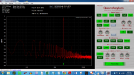
Ok, so I went back to the bnc/banana connectors and rebuilt the network with a 260 ohm resistor ( measured at 267.4 ). The spreadsheet says to expect 0.599 Volts on a true RMS voltmeter when sending out a 60 Hz signal at -14 dB I did this from the QA400 and the meter read 0.598 Volts. The divider is working perfectly.
The next bit was to try the alligator clip. I did not even see a fundamental. There was nothing but noise.
So, I hooked up the BNC to the end of BNC to banana adapter ( across the banana is the 260 ohm resistor). I got the attached. And the H2 is bigger than H3. There is an adjustment pot that can adjust this, so that H2 can be equal to H3 or perhaps even below.
The nasty noise is still there, but this looks like a useable chart. Note the fundamental is very close to what it ought to be. I will redo this test when the new cables arrive.
Richiem: Thanks for pushing to rebuild the divider. It looks decent now, but the noise is still high. Let's hope that is just EMI.
Attachments
Last edited:
Bear,
The MOSFETs are matched Fairchild from buzzforbs group buy.
The source resistors are Fukushimas and were matched by Horio to insane levels.
The bias voltage is 0.275 volts
The transformer is a 2.4 KVA toroid, with multiple primary taps, wired to provide 34 VAC, and 1.4 KVA. There are 5 center tapped secondaries ( total 15 wires on the secondary side ). I am using two sets of secondaries per channel. This makes about 580 VA per channel. One CT is not being used. It is an encapsulated toroid ( Plitron surplus stock ).
The jfets were closely matched by another DIYaudio guy.
The cascodes are the from the schematics -- dunno the make.
There is an auxilliary 12 VAC 20 VA transformer that feeds a regulator which is controlling the soft start, slow charge ( 2 x 555 timers ) and the speaker protection circuits. It is encapsulated - SumR.
The wiring is taken from stripped down 14/3 house wiring from home depot. All wiring is twisted.
The rectifiers are 3020's, there are four banks of CRC ( one per rail per channel ), where C = 44,000uF, and R = 0.5 ohms. This will be converted to CLC some time soon, using 4.5mH Erse SuperQ inductors.
The main audio ground is at the same point as the safety earth. Each channel is grounded to the safety earth using a CL-60 and a diode bridge as per Nelson Pass.
One issue may be that the Front end boards are on the rear of the amp, while the cap banks are at the front. This means ground and power must run from front to back. I have not implemented this well, as both power and ground run through the output boards..... This makes a big loop.
However, the chart produced on this thread shows no noise when the input from the analyzer is removed. If there was an issue with the grounding scheme, I would expect to see noise.
@BigE -- not meant to infer a criticism; just a lot of experience with amps and their owners. Sorry, it's actually not about you.
Now, as to levels -- you should shoot for an input to the QA400 of about 600mVRMS at 1kHz, according to the local lore around here, as that apparently gives the QA400 its own best distortion performance while preserving adequate dynamic range.
So, if you want your amp to be measured at 1W into 8 ohms(?) then you want 2.83VRMS output from the amp across your 8 ohm load. BTW, is this amp a Class A amp? I ask because I'm not familiar with it.
I personally would give my divider an attenuation of about 12dB, but I would put a 100ohm pot as the bottom leg of the divider so that I could easily set my amp output level, then dial in the best input level to the QA400, which will be at around the -6dB level on the plot; but using -10dB as the ref level makes all the math easier.
I think that there are real grounding issues with the output of the amp, and that your intent to use the QA190 diff probe was a well-founded one. Since I don't have one, I can't comment on using it, but you're not getting the signal level you want in part because the ground reference is not right at the amp output. This is the kind of measurement hassle that results from using a signal generator and analyzer that share a common ground, and is why HP and Sound Tech and many others use balanced inputs and/or outputs on distortion analyzers.
I know the advice to not use the QA190 was well-intentioned, but I think that it is exactly what you need. I also am of the opionion that you are measuring in the middle of substantial magnetic interference (EMI) and that dealing with that is really a difficult issue, because ground loops are nearly inevitable.
Hang in there -- you are making progress. And everyone here is also ready to help.
It's one of Nelsons so it going to be class A.
I did notice that when the bias was raised, the amp got a bit punchier -- got to 0.3 volts across 4 pairs per channel.
But I am almost up to the limit of the heatsinking at this point. The heatsinks go to 49 deg C right now. It is 0 degrees Celsius outside, and the amp is the only source of heat in the basement.
My friend built an F5 as well, and the nasty noise is also there in his amp. This again points to shielding of cables. ( At least in my mind ).
- Home
- Design & Build
- Equipment & Tools
- QuantAsylum QA400 and QA401