@BigE -- I would test at 4W (5.66VRMS) output because the distortion curve Pass shows has sufficiently high THD at 4W, that measuring yours vs. his is much easier for both you and the QA400.
RE shielding, Mu metal is only good when actually annealed with it in its final shape -- once it is annealed and then bent or folded or banged around it loses it's shielding goodness, and mild steel works every bit as well. Hence the small garbage can or a waste can with a good lid -- the little garbage cans are cheaper around here than anything else. I priced a steel electrical housing and nearly fell over at the $45 price tag for a box of about 1/2 cu ft. You're going to have to get cables in and out of whatever you use, and small holes are not a big problem. You may get the isolation you need by just physically moving away from the amp, but it sounds like your work area is a tangled mess of EMI and RFI...
RE shielding, Mu metal is only good when actually annealed with it in its final shape -- once it is annealed and then bent or folded or banged around it loses it's shielding goodness, and mild steel works every bit as well. Hence the small garbage can or a waste can with a good lid -- the little garbage cans are cheaper around here than anything else. I priced a steel electrical housing and nearly fell over at the $45 price tag for a box of about 1/2 cu ft. You're going to have to get cables in and out of whatever you use, and small holes are not a big problem. You may get the isolation you need by just physically moving away from the amp, but it sounds like your work area is a tangled mess of EMI and RFI...
On the amp input: business as usual.
On the amp output: using a BNC to alligator clip cable, attach the red clip to the 1K/10R junction, but do not attach the black clip to the speaker return binding post/1K junction.
Let me confirm I have the details right.
Amp output in the measurements is 2.83V RMS
That should be 28 mV RMS at the QA400 input with the 100:1 divider I proposed. In this plot you show an input level of .68 mV. That's about 35 dB low. Figuring out why will help understand what the problems are.
If you are running the amp at 2.83V a 20 dB attenuator (10:1 divider) would be fine and would allow for accurate voltage level assessment. Be careful not to push it much harder or you can fry the QA400.
The hum voltages below 10 mV are usually inaudible on speakers. That would be about -50 dB on these plots. If you set the plot to dBV its easier to gauge actual voltages from the signals. The Flat Top is good for measuring a signal's level. Its not good for looking at low level noise etc. Use the Hann window for looking at harmonics.
You describe a noise issue as well, can you describe the noise any more specifically?
Thanks Richiem.
@1audio: Will give details tomorrow and report on the effect of the longer cables. Bedtime is nigh.
@1audio: Will give details tomorrow and report on the effect of the longer cables. Bedtime is nigh.
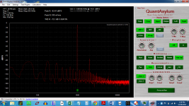
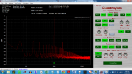
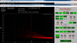
The results of the longer cables. Included is a chart with the hot output only. This is a snapshot, as it bounces up and down quite a bit. Will retest with Hann, and will change to dbV. The resistor divider is 1K/270 Ohms. Signal taken at 1K/270 Ohm junction
Attachments

Last edited:
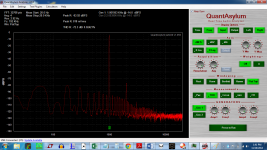
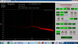
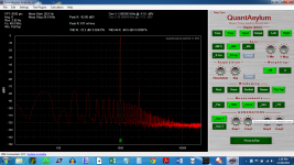
Hann and dbV. The resistor divider is 1K/270 Ohms. Signal taken at 1K/270 Ohm junction
Attachments

Last edited:
Boy, these measurements have come a long way! I have to say thanks for all the support and help on this forum.... simply excellent!
1audio, the noise issue is just that noise you see in the charts, obscuring the harmonics. So yes, a stronger output signal with appropriate divider would be the trick.
My spreadsheet says: 0.8 volts in, 23dB gain, 11.3 V out, 1000/100 ohm divider => 1.023 V to analyzer, and 15.5 watts into 8.2 ohms, which will fry my load resistor. I will need to obtain a proper 8 ohm resistor to make these higher power measurements.
My spreadsheet says: 0.8 volts in, 23dB gain, 11.3 V out, 1000/100 ohm divider => 1.023 V to analyzer, and 15.5 watts into 8.2 ohms, which will fry my load resistor. I will need to obtain a proper 8 ohm resistor to make these higher power measurements.
Yep, you're3 in the zone now. Better shielding is next step, then everything you see will be real.
OK, so I am on the hunt for a cheap steel can. A small garbage can ought to do. It just has to be magnetic correct?
The long cables mean I can put the laptop on the coffee table. It's much more convenient.
BTW: I get some sort of signal opening the speaker protection relays on the amp when I insert the USB cable into the laptop while the B end is in the QA400.
The long cables mean I can put the laptop on the coffee table. It's much more convenient.
BTW: I get some sort of signal opening the speaker protection relays on the amp when I insert the USB cable into the laptop while the B end is in the QA400.
Is the laptop running on wall power? If so, run it on batteries. If not, really don't have a clue.
It is on battery.
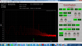
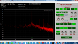
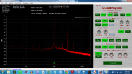
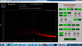
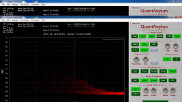
I just plugged in all over again, now the amp has been left ON for two days. I got some very different results. I have an enameled steel can with a lid, and putting the unit into the can makes no difference. The second shot is with the pump for the home heating going. Actually, I now think that is the compressor for the fridge.
I just plugged in all over again, now the amp has been left ON for two days. I got some very different results. I have an enameled steel can with a lid, and putting the unit into the can makes no difference. The second shot is with the pump for the home heating going. Actually, I now think that is the compressor for the fridge.
Attachments
Last edited:
My resistor ladder fell apart...
Here are the new shots.
Here are the new shots.
Attachments
Last edited:
FYI -- including the steel garbage can, I was testing directly under a ceiling light (of course). it is a florescent type. Turning it off helps also.
Also other equipment not being used needs to be turned off.
THx-RNMarsh
Also other equipment not being used needs to be turned off.
THx-RNMarsh
What's the set-up diff between these plots -- the second is quite good.
The first image is the right channel, the second is the left.
I fried the right channel once, and replaced all the P channel devices. I was fooling with P3 on the front end board. Also, during early development, the output shorted, and a wisp of smoke arose from a capacitor in the PS section. Removing and measuring the caps showed no problems, so I continued with it. Maybe they should all be replaced.....
Another difference is that the pot P3 is not bourns on the right channel. I want to try to set P3 to lower the distortion -- it is a feature of that pot. And the entire purpose for this analyzer.
I think I will give it a shot.
Nice. You may be near the adjustment "graininess" limit anyway. But turn off averaging while you tweak the pot to see a rapid update which makes tweaking easier.
BTW, I think I madly misinformed you about the S/N as reflected by the divider -- the S/N you see on the plot is the S/N, no need to add or subtract anything.
BTW, I think I madly misinformed you about the S/N as reflected by the divider -- the S/N you see on the plot is the S/N, no need to add or subtract anything.
Thanks. I guess that the can ought to be all metal, and not enameled metal. I'm guessing that you want metal on metal contact?
I've turned off the lights as well, to no effect.
There was a slight decrease in the number of low frequency peaks when it went into the enameled can.
Will try again later. And will take some photos of the divider once I retrieve my camera. Perhaps after next weekend.
I have to thank everyone for helping me get this far. I hope that logging all of this helps others use the tool.
I know at least one other person that would like to borrow this for the same purpose.
I think the can is just not the right stuff. You want a thick mild steel with a cover that is metal-to-metal contact. You could try scraping off the enamel at several contact points and see what happens...
- Home
- Design & Build
- Equipment & Tools
- QuantAsylum QA400 and QA401