My job has me in and out of e-rooms of different buildings through out the year.
I have found floating grounds (floating neutrals) in some of these building. The ground connectors simply loosened up or become so corroded they're not doing anything.
It wouldn't hurt to check this in your building.
I have found floating grounds (floating neutrals) in some of these building. The ground connectors simply loosened up or become so corroded they're not doing anything.
It wouldn't hurt to check this in your building.
Last edited:
I have found floating grounds (floating neutrals) in some of these building. The ground connectors simply loosened up or become so corroded they're not doing anything.
Also, Aluminum house wiring is prone to loose connections -- we had some in our house and a lot we replaced.
At the time aluminum wiring was introduced, on occasion the electrical contractor would neglect to use "Al/Cu" outlets which led to house fires.
Is this why you're not supposed to store auto batteries on a concrete floor? For all i know that suggestion might be urban myth. Nevertheless, there seem to be quite a number of papers from engineering schools on the conductivity of concrete slab.
I have heard that for years and maybe with a hard rubber case there was some validity, but a steel bracket for a battery in a plastic case won't discharge the battery and a concrete floor will???
You may have a wiring issue in the house. If the current was going around your space in a large loop instead of in paired wires like Romex you could have a strong field inside of it. This if the case would also imply a safety issue.
You could make a quick mag field probe out of a speaker inductor or wire around a magnetic iron rod or bolt and just explore with the QA400 to see where the field is strongest .
I tried once just lifting the QA400, and found that when lifted to the right of my workbench, the noise increased... but it had to be lifted. This it nearer the location of gas feed for the house. I believe that the earth ground is still on the water pipe.
I'm going to put the small loopback cables on and go for a walk about.
If you are on a concrete floor, it can induce some very nasty power junk. The rebar and the concrete itself are conductive and often have more than you would think, or want, ground noise. You MAY be able to reduce it by turning off the main breaker to the house, then again you may NOT. Harmonics in the power grid for your location may be there regardless of what you do. It's all fun and games!
If lifting the piece off the floor reduces the interference, then you have ground current flowing thru your building.
Cheers,
Alan Garren
I have no rebar. This house was built in 1925. The wiring in the basement has been modernized.
There is an outlet upstairs near that gas feed that I think may have been repaired as well.....
Hopefully, there is no circular link installed. I know there was some tomfoolery done.... perhaps the electrician unknowingly created a loop?
with the conversion of many systems to PEX and other plastic pipes, bonding to the water system is not necessarily a good idea. It is also not up to code in most areas. A well built ground rod and its secondary are the starting place for adequate ground systems.
housing of that age needs (wants?) to have its full electrical system inspected, you may find many short cuts that have been made over time.
Alan Garren
housing of that age needs (wants?) to have its full electrical system inspected, you may find many short cuts that have been made over time.
Alan Garren
Last edited:
It's a myth about the batteries on concrete floors.
Acid batteries discharge on there own resistance. I have some 12V gel cells at work that ran them selves down so much our conductance meter can't measure them. They have to be fully charged to do a conductance measurement on them. Gel cells are acid batteries with silicate dissolved into the solution.
The problem with acid batteries discharging is it leave a coating of sulphate on the plates.
If enough sulphate build up, the battery won't take a charge. An acid battery that is completely discharged contains sulphate on the plates and water. When acid batteries are charged the process is reversed. The sulphate reverts to sulphuric acid. Also spelled sulfuric.
I tried once just lifting the QA400, and found that when lifted to the right of my workbench, the noise increased... but it had to be lifted. This it nearer the location of gas feed for the house. I believe that the earth ground is still on the water pipe.
I'm going to put the small loopback cables on and go for a walk about.
I have no rebar. This house was built in 1925. The wiring in the basement has been modernized.
There is an outlet upstairs near that gas feed that I think may have been repaired as well.....
Hopefully, there is no circular link installed. I know there was some tomfoolery done.... perhaps the electrician unknowingly created a loop?
Canadian electrical code requires the grounds to be done in two ways. To a buried ground plate or rod and to a water pipe. One needs to check both.
This is definitely a metal pipe. The house is 90 years old. No conversion here, as the basement reno was done on my watch.
In the US a water pipe is not acceptable as a ground. The proper process is a seperate ground rod and check it with the special checking system. Of course the code says if one doesn't work add a second and don't bother which is really kind of dumb. A friend of mine consulted on an electrocution death that was a consequence of this type of nonsense.
Loops do happen. I had one here. Caused all end of confusion with two breakers feeding my shop. Never could figure it out but disconnected one breaker for safety.
In any case the gas pipe should not have current on it unless you want to be a headline in the morning news.
Loops do happen. I had one here. Caused all end of confusion with two breakers feeding my shop. Never could figure it out but disconnected one breaker for safety.
In any case the gas pipe should not have current on it unless you want to be a headline in the morning news.
There is a GU-20 light in that vicinity. It seems that even when those lights are off, there is still an issue. I'm going to make that mag field checker.
SO this is just a loop of wire around a piece of metal ( like a file ) that is connected between signals of two BNC cables from in to out?
SO this is just a loop of wire around a piece of metal ( like a file ) that is connected between signals of two BNC cables from in to out?
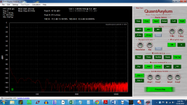
OK,so I got this MARVELOUS shot by holding an 8" metal file wrapped in stranded 18 awg hookup wire connected between two alligator clips while in loopback mode.
Same at the back where the speaker posts are... I assume that at the rear, it is radiating from the unshielded power cord. I will borrow a shielded one and see if that helps.
This seriously looks like diode switching and harmonics from MUR3020 diodes.
Would snubbing work? Should I just follow Quasimido's rules? (Mark Johnson's bell ringing snubber).
Attachments

There is a GU-20 light in that vicinity. It seems that even when those lights are off, there is still an issue. I'm going to make that mag field checker.
SO this is just a loop of wire around a piece of metal ( like a file ) that is connected between signals of two BNC cables from in to out?
Simpler-
A coil of wire (with or without the file) from BNC hot to BNC shield. Connect to the QA400 input. Turn off the source side of the QA400 and start a continuous measurement. You should see 60 Hz and it will go up when you move the coul near an active power transformer for example. if the transformer has a rectified load you will see a lot of 120 Hz and harmonics. If loaded with an incandescent light bulb or a resistive heater it will be mostly 60 Hz.
These are ideal for this: Item # EP-101A, AC Probe-Axial-20 mV On Magnetic Shield Corporation and do pop up on ebay for lots less than $70.
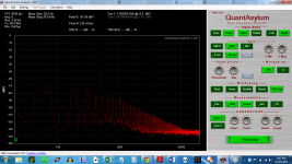
OK four shots with that method, around an 8" file.
First is at the diode bridge at the front of the amp
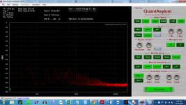
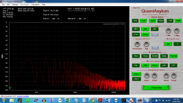
Second is at the power cord at the back of the amp
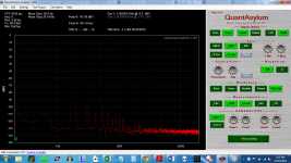
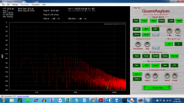
Third is across the room at my workbench.
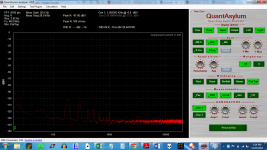
Fourth is in an enamelled steel can
There is no difference when the QA400 is placed in this can.
First is at the diode bridge at the front of the amp
Second is at the power cord at the back of the amp
Third is across the room at my workbench.
Fourth is in an enamelled steel can
There is no difference when the QA400 is placed in this can.
Attachments
Last edited:
Time to look at the wiring around the transformer, bridge and caps. They should all be tightly twisted pairs minimizing the loop area so the radiation is minimized. There is a lot of harmonic energy around the rectifier. The LF falls off but the harmonics radiate further which may make sense.
Follow each current as a loop. Go from where it originates, e.g. power cord line to switch to fuse to transformer to power cord neutral. The area inside that loop need to be as close to zero as possible even if you need more wire to make it work. Transformer secondaries to rectifier to caps. Keep the centertap close to the other two wires or you have a 1/2 wave loop on each cycle.
Follow each current as a loop. Go from where it originates, e.g. power cord line to switch to fuse to transformer to power cord neutral. The area inside that loop need to be as close to zero as possible even if you need more wire to make it work. Transformer secondaries to rectifier to caps. Keep the centertap close to the other two wires or you have a 1/2 wave loop on each cycle.
It's all tightly twisted except that the center tap is independent of the other two voltages.
I am going to try to reduce the loop areas, but I am using a bunch of relays for the slow-charge circuit. So the wiring may not be as tight as would otherwise be expected.
I hope the issue is just at the diode bridge, though I may have to rewire that a bit. The center tap wiring heads straight for the cap bank, while the diode bridge is off to the side of the amp.
All of these circuits were mounted on the faceplate of the amp. Maybe they ought to be reorganized more sensibly? I will check through it with the coil of wire tomorrow, with the top off.
THANK YOU FOR YOUR HELP!
The replacement scope is on the way, so I will be able to snubberize the transformer.
Last edited:
Wind the centertap with the leads from the transformer and on to the caps. Every 1/2 cycle the current goes through 1 diode, lead from the transformer and one lead to the caps, next 1/2 cycle through the alternate lead. Always returning through the centertap.
Its a common mistake since it seems that there would be no current through the centertap but there always is. You can take the current clamp from the QA190 and clamp that around the leads and see what is happening. Use the waveform view on the QA400 to see the waveform. It will not be pretty.
Its a common mistake since it seems that there would be no current through the centertap but there always is. You can take the current clamp from the QA190 and clamp that around the leads and see what is happening. Use the waveform view on the QA400 to see the waveform. It will not be pretty.
OK, so I need to make a braid.
I wired the secondaries to a barrier strip so that I could feed a single pair of wires to the rectifier, instead of two pairs... you see my transformer has 5 Center tapped secondaries. I connect the secondaries at the barrier strip prior to going to the rectifier, and leave one set of CTapped secondaries unused.
I was trying to use this boat anchor of a transformer for something.....Please don't tell me I will need to buy more iron!
Last edited:
Here are a couple of "before" shots, looking for problem areas, with about 20 turns of wire wrapped around a metal file, then the file is taped from end to end with electrical tape, in case I drop it.
The first shot is with the sensor away from the DUT. Note how low the magnetic field tester is reading.... this is "ambient".
The second is under the amp, at the left channel barrier strip... I have included a barrier strip between the secondaries and the slow charge circuit ( which lives on the faceplate of the amp, along with the rectifiers and cap banks.). The intent is to be able to easily remove the toroid in the event that the amp needs repairs.
The third is under the barrier strip that connects right channel secondaries to the rectifier.
From here, the secondary wiring goes to two diode bridges, one per channel.
Visual inspection shows that the right channel twisting of the secondaries to the barrier strip is not as tight as the left.
Also, since the circuit path is Toroid -> barrier strip -> rectifier ->blocking relay -> thermistor || bypass relay -> cap bank, I think I can replace the barrier strip with the blocking relay, thus losing quit a bit of open loop area.
The circuit would then go:
Toroid -> blocking Relay -> rectifier -> thermistor || bypass relay -> cap bank.
This will take some work....
THANKS!
Perhaps it is best to simply move the toroid and main power supply away from the amp?
Attachments
Last edited:
the slow start relay, if that is what it is, is best positioned in the primary, not the secondary.
I'm unclear on what a blocking relay is. I presume the bypass relay parallels the thermistor?
Again I prefer to put all the soft start stuff in the primary.
Perhaps you might want to do that.
Also run a test with the relays and thermistors out of the circuit, use a variac
to bring up the amp slowly. Alternately, a lightbulb (or resistor) in series with the primary, with a hard switch to bypass it (a relay is fine).
Are you sure you have all the secondaries in phase ?
How do you know?
How hot does the toroid run?
Are you below the VA rating of the toroid when it runs the two channels?
Does the amp exhibit the extra "junk" when running only ONE channel?
How is the chassis grounded? Did you try a hard ground, just to see if that has any effect? (I think ur using the bridge + cap method)
The question in my mind is if this picked up "junk" is being induced into the output or is actually on the rails. Have you looked at the rails with a scope??
If ur scope has an output for the vertical amp, perhaps you might run that into the QA while you probe the rails. You won't get the full S/N, but you don't need it. You'd be looking for the "junk" on the rails... then you can look for the junk on the + and the - rails and see if they are in phase or out of phase. The noise you are seeing is looking a lot like in phase noise, UNLESS the source of the noise is HUGE and this is badly cancelled residual.
IF the junk is NOT on the rails, then the junk may be coming into the input. In which case if you short the input on the board and maybe detach the input wires (where do they run?? what are they??) and it goes away, then ur problem is suddenly known.
_-_-
the slow start relay, if that is what it is, is best positioned in the primary, not the secondary.
The soft start is positioned on the primary. It is the DIYaudio soft start.
I'm unclear on what a blocking relay is. I presume the bypass relay parallels the thermistor?
This relay blocks the voltage from the transformer from reaching the thermistor. The point of it is to provide a delay that will enable the thermistor to cool, in the event that the user power cycles the amp say 45 seconds after power on. At that point, the thermistor is hot, and will not lower inrush current if power is cycled.
The cooling time for the thermistors to become sufficiently protective for the 88,000 uF per rail per channel is 1 minute. A 555 timer circuit closes the blocking relay after one minute so that the secondaries can provide power to the thermistors(1 per channel). The secondaries are wired to the NO contacts.
A second relay bypasses the thermistor after another minute. LTspice was quite clear that the second inrush caused by bypassing the thermistor would take another minute delay to get under 20 A. So, after a minute the thermistor is bypassed, the amp is ready to go.
Bear said:Also run a test with the relays and thermistors out of the circuit, use a variac
to bring up the amp slowly. Alternately, a lightbulb (or resistor) in series with the primary, with a hard switch to bypass it (a relay is fine).
Not to sound flippant, but what for? The size of the cap bank requires a slow charge circuit. It *must* work with the slow charge circuit installed.
EDIT: OK... it will clearly show that the problem is in the slow charge or not.
Yes. I measured their relative phases. Not hot.Bear said:Are you sure you have all the secondaries in phase ?
How do you know?
How hot does the toroid run?
Bear said:Are you below he VA rating of the toroid when it runs the two channels?
Yes. The amp has been on now for a solid week.
Bear said:Does the amp exhibit the extra "junk" when running only ONE channel?
I don't understand what that test will show. The measurements above coincide with a visual inspection showing that the right channels twisting of the secondaries is looser than the left. Also, that the center tap is nowhere near the secondaries, as it connect to the PS ground directly.
I will likely be addressing this wiring problem tomorrow.
Bear said:How is the chassis grounded?
Third prong/safety earth.
Bear said:Did you try a hard ground, just to see if that has any effect? (I think ur using the bridge + cap method)
I am using a ground loop breaker from the zero volt line to the safety earth at a single point -- the safety earth. Hard ground is noisy. This was the first issue with the build that was solved.
Bear said:The question in my mind is if this picked up "junk" is being induced into the output or is actually on the rails. Have you looked at the rails with a scope??
The scope is in transit... it arrived DOA a few weeks ago, and a new one was sent out late last week.
The scope that is coming is a Rigol DS1102 I don't think is has a vertical output.
Given the charts from the DIY magnetic probe, it appears that the junk is induced on the rails. The junk looks the same at the barrier strip as it does the output. It is worse near the rectifiers. Once the scope arrives, I will add an R-C snubbing network.
I think there are two issues here. The ultra low frequency noise from the wiring, and the switc hing noise from the diodes.
Why do the caps not smooth the noise out?
Bear said:If ur scope has an output for the vertical amp, perhaps you might run that into the QA while you probe the rails. You won't get the full S/N, but you don't need it. You'd be looking for the "junk" on the rails... then you can look for the junk on the + and the - rails and see if they are in phase or out of phase. The noise you are seeing is looking a lot like in phase noise, UNLESS the source of the noise is HUGE and this is badly cancelled residual.
IF the junk is NOT on the rails, then the junk may be coming into the input. In which case if you short the input on the board and maybe detach the input wires (where do they run?? what are they??) and it goes away, then ur problem is suddenly known.
_-_-
Thanks! I will short the input and measure..... if I recall, that did nothing. Each input is a well twisted pair of 20 AWG solid core wire. Each are about 1.5" long.
I am going to try a couple of things... one is to move the relay that implements the 1 minute delay from power on to in front of the diodes, which then replaces the barrier strip, and ought to clean up one section of wiring.
When I do this, I will twist the wiring everywhere into much better shape -- It will probably require splicing to the secondaries.
The real issue may simply be that the toroid is too darn close to the slow charge relays, and that is where the noise enters. It may be smarter to make this a two box affair, and keep those relays far from the toroid. The toroid is a potted, but not electrostatically shielded Plitron.
Thanks bear, I hope I have explained everything, if not, please ask!
Answering your questions helped me see that there really are two issues here..... wiring and snubbing.
Last edited:
- Home
- Design & Build
- Equipment & Tools
- QuantAsylum QA400 and QA401