@David
What makes you think that the USBStreamer is unsuitable for a high performance ADC?
On its own perhaps, but not with a suitable interface, as I have described.
If you feel that I have overlooked something, please let me know.
Jens my comments have nothing to do with your design or efforts. It's based solely on the research I've done. Some of what I've said about the USB streamer is forward and not to be taken as absolute. I haven't done any phase noise measurements on it. The architecture of the design alone says it all. It's bad news to run an ADC as slave. PLL is not a solution because PLL generates some phase noise. PLL is fine for re-sampling data. The best performance is to favor the ADC with it's own dedicated low noise clock. Once the samples are had then things are not so restrictive.
Read the articles I linked to. If you haven't done phase noise measurements on your design then the performance is assumed. That's okay but you can't say with certainty that it meets any particular level of performance.
What I'm doing is interfacing an ADC with the miniDSP's USB streamer. Unfortunately the USB streamer cannot be set as IS2 slave. It operates in master mode only. I would prefer the ADC to be master.
Are you sure? I contacted them and they said there's jumper or switch on there somewhere for master/slave.
The easiest path to a DIY instrumentation-grade audio frequency range ADC seems to get one of those semi-pro (UBS?) audio interfaces that support ASIO drivers and accept an AES-EBU/SPDIF/TOSLINK input, and to build a master-only ADC (e.g. around the PCM4222 chip).
Regarding clock selection: the Crystek CCHD-957 I linked above is surely good enough even for critical audio applications. Also still reasonably priced and stocked at Mouser. But it's not voltage controlled, so it can only be a master clock, not within a PLL.
Samuel
I'm certainly interested in this, but I don't have the skill or the knowledge to design my own circuit board. Otherwise, I would have been done with this months ago.
Would it be wise to keep the crystal on all the time, in order to stabilize it's performance? Is that what "standby" mode is for?
Having been down these roads here is what i found works-
Both USB (EMU 0404) and PCI interfaces work great over SPDIF. USB is less stable and can be sensitive to other USB traffic. The PCI interfaces are more solid (RME, EMU 1212 or ESI Juli@) are more robust. The TI PCM4222 demo board works pretty well, but its performance is not in the same league as the AKD5394A demo board. Making one from scratch looks really interesting but becomes quite the project. I know of two other efforts underway as well. I'm planning to make an upgrade card for the Juli@, but its on hold pending evaluation of the new AKM ADC.
I don't want to have to buy another computer with PCI slots in it, so my preference is for USB or firewire. I was planning on using the PCM42222 demo board but I damaged it getting the XLR's off of it. They didn't plan on anyone using this demo board in a real box.
Are you sure? I contacted them and they said there's jumper or switch on there somewhere for master/slave.
The user manual states the USBstreamer operates in master mode only. If there is a way to select between master and slave mode it's not mentioned. Can you forward me a copy of the email if you still have it. There is a jumper header and shunt on the board which is not documented but I assume this was for USB powered or external powered selection.
There is another group of header pins on the board but I don't know what they're for. Also not documented in the user manual.
I tend to agree about buying a PCI computer.... it sort of defeats the idea of small and portable. It becomes a bench instrument. ----though the cost to performance ratio may be high.... it comes with too much baggage for me. I too have wondered about just using a great demo board in a box with desired or appropriate I/O interfacing. Might not be the absolute cheapest of all time, but also gives a lot of Bang for the Buck and nearer to SOTA performance. And, without reinventing everything along the way. Just focus on what design is needed to make it more useful as a test instrument. Let's jump-start this thing by buying as far along into predevelopment as possible.
The QA400 and a notch filter is the cheapest way to go. Next up the line it follows the exponential rise in cost for more performance. The demo board seems to be the practical DIY'er answer for higher performance. And, beyond that level the curve is long and steep.
Thx-RNMarsh
The QA400 and a notch filter is the cheapest way to go. Next up the line it follows the exponential rise in cost for more performance. The demo board seems to be the practical DIY'er answer for higher performance. And, beyond that level the curve is long and steep.
Thx-RNMarsh
Last edited:
I don't want to have to buy another computer with PCI slots in it, so my preference is for USB or firewire. I was planning on using the PCM42222 demo board but I damaged it getting the XLR's off of it. They didn't plan on anyone using this demo board in a real box.
You can fix the damaged PCB. I can't imagine you completely destroyed it removing an XLR.
Firewire is interesting but I only see pro gear for that in the big $. The idea is to find a workable solution that doesn't place it out of $ range for DIY. I did that with my oscillator but then it's intended for me. There is dedicated i/o boards for broadcast but again into the big $.
When I say PCI I mean an in box card of some sort. I suppose this is no help for laptops and notebooks.
The user manual states the USBstreamer operates in master mode only. If there is a way to select between master and slave mode it's not mentioned. Can you forward me a copy of the email if you still have it. There is a jumper header and shunt on the board which is not documented but I assume this was for USB powered or external powered selection.
There is another group of header pins on the board but I don't know what they're for. Also not documented in the user manual.
MiniDSP :: Topic: Re: miniStreamer with TI's PCM4222EVM? (1/1)
Ask them for more information if needed.
You can fix the damaged PCB. I can't imagine you completely destroyed it removing an XLR.
Firewire is interesting but I only see pro gear for that in the big $. The idea is to find a workable solution that doesn't place it out of $ range for DIY. I did that with my oscillator but then it's intended for me. There is dedicated i/o boards for broadcast but again into the big $.
When I say PCI I mean an in box card of some sort. I suppose this is no help for laptops and notebooks.
I have traces up in the air.... sigh... There's no holes for mounting the board to anything, just 4 rubber bumpers stuck on the bottom, which is another problem. I don't like half *** solutions so I just gave up.
Separate PCI boxes that interface with laptops are expensive ($375) the last time I looked, though I agree it would be a cool solution if I had a spare PCI slot in some existing computer, which I do not. I only have laptops...
Last edited:
I tend to agree about buying a PCI computer.... it sort of defeats the idea of small and portable. It becomes a bench instrument. ----though the cost to performance ratio may be high.... it comes with too much baggage for me. I too have wondered about just using a great demo board in a box with desired or appropriate I/O interfacing. Might not be the absolute cheapest of all time, but also gives a lot of Bang for the Buck and nearer to SOTA performance. And, without reinventing everything along the way. Just focus on what design is needed to make it more useful as a test instrument. Let's jump-start this thing by buying as far along into predevelopment as possible.
The QA400 and a notch filter is the cheapest way to go. Next up the line it follows the exponential rise in cost for more performance. The demo board seems to be the practical DIY'er answer for higher performance. And, beyond that level the curve is long and steep.
Thx-RNMarsh
IMO
I tend to agree about buying a PCI computer.... it sort of defeats the idea of small and portable. It becomes a bench instrument. ----though the cost to performance ratio may be high.... it comes with too much baggage for me. I too have wondered about just using a great demo board in a box with desired or appropriate I/O interfacing. Might not be the absolute cheapest of all time, but also gives a lot of Bang for the Buck and nearer to SOTA performance. And, without reinventing everything along the way. Just focus on what design is needed to make it more useful as a test instrument. Let's jump-start this thing by buying as far along into predevelopment as possible.
Thx-RNMarsh
I like the idea of keeping things modular. This way upgrades are doable without reinventing the wheel. An ADC driving a transmitter and perhaps a an isolated I2S port provides this. Then it's not married to anything. It can be used with a USB dongle or PCI which ever. A transmitter ends the argument over who's boss master or slave and offers isolation.
A few observations from the pile of less than ideal stuff I have.
1) The PCI interfaces work the best, few problems with data collisions etc.
2) XP works better since the XP sound engine does get out of the way. In Win 7 (8?) it want to resample everything and you need to set it for every sample rate and format change. Linux would be ideal but the tools are less developed.
3) The USB interfaces do not work as well. They work but many little things jump out to bite. For example getting the EMU 0404's spdif to run in full duplxs at 192 does not seem to be possible.
4) My best solution right now is an EMU1616M + cardbus card. I'm probably going to find the hottest laptop with a cardbus slot I can and load an SSD with Win XP on it. The 1616M is fully isolated from the host with transformers at each end of the cable. To get better performance will be difficult. It has the AK5394A in a very good implementation (X3) plus a lot of other less important interface things.
I have been kibitzing on Jens' AD-DA module and its very good. I think it will have better performance than the 1616M when its done. he has the Minidsp running in slave mode for the master clock. This is a perfectly fine solution. If someone tweakes the firmware to get the minidsp to run in full slave mode it would be even better. I know its possible and the guys at Minidsp would be the best source. Worst case maybe we can fund a little development on their part. For the target audience they have adding slave mode to the box would make implementation with the other DSP modules really complex.
MiniDSP :: Topic: Re: miniStreamer with TI's PCM4222EVM? (1/1)
Ask them for more information if needed.
The advice is to set the miniStreamer as master and the pcm4222evm as slave.
I have the USBstreamer big brother to the mini. Setting the streamer as master suggest it is possible to chose but this might not be possible with the USBSreamer. I'll fire some questions off to miniDSP.
A few observations from the pile of less than ideal stuff I have.
1) The PCI interfaces work the best, few problems with data collisions etc.
2) XP works better since the XP sound engine does get out of the way. In Win 7 (8?) it want to resample everything and you need to set it for every sample rate and format change. Linux would be ideal but the tools are less developed.
3) The USB interfaces do not work as well. They work but many little things jump out to bite. For example getting the EMU 0404's spdif to run in full duplxs at 192 does not seem to be possible.
4) My best solution right now is an EMU1616M + cardbus card. I'm probably going to find the hottest laptop with a cardbus slot I can and load an SSD with Win XP on it. The 1616M is fully isolated from the host with transformers at each end of the cable. To get better performance will be difficult. It has the AK5394A in a very good implementation (X3) plus a lot of other less important interface things.
I have been kibitzing on Jens' AD-DA module and its very good. I think it will have better performance than the 1616M when its done. he has the Minidsp running in slave mode for the master clock. This is a perfectly fine solution. If someone tweakes the firmware to get the minidsp to run in full slave mode it would be even better. I know its possible and the guys at Minidsp would be the best source. Worst case maybe we can fund a little development on their part. For the target audience they have adding slave mode to the box would make implementation with the other DSP modules really complex.
I'm a DIY at heart and always have been.
OK, I think I need to clear up this whole issue. Having analyzed the working principle of the USBStreamer and made a modification to the clock system I have a pretty good understanding of what can be done and what cannot.
@dirkwright
It is correct that the USBStreamer can (in an unmodified state) only work as a clock master. This is stated in the manual. There is no jumper to change that.
I am pretty sure that when MiniDSP writes "configure the miniStreamer as I2S master and you should be set." they really mean "configure the PCM4222 ADC evaluation board as slave, with the miniStreamer as master". Note by the way that this was in the miniStreamer forum. The USBStreamer is a completely different animal compared to the miniStreamer. The USBStreamer is much better in many respects. I have worked with both, but the miniStreamer has so many limitations that I don't really want to use it.
As davada points out in post #890 the USBStreamer generates all the clocks from the on-board 13 MHz oscillator. The 13 MHz is multiplied in the XMOS and divided down again to a 300 Hz clock. The 300 Hz clock is used by an external clock PLL to generate either 22.5792 MHz or 24.576 MHz depending on the sample rate (44.1 or 48 kHz multiples).
This clock is used for the MCLK and the SCLK and LRCK are derived from this clock. Due to the two PLL's and probably also the rather low reference frequency (300 Hz) there is a relatively large amount of jitter on the clock outputs.
@davada
As you write "The TOSlink input operates as a slave but only to 176kHz." This is also specified in the manual. However it is possible to make it work at 192 kHz. I had a communication with MiniDSP regarding this and they kindly sent me a new pair of Toslink transmitter and receiver. After replacing the Toslink devices it was possible to make it work at 192 kHz. But it seemed to work with a very small margin, so it could easily fail, if conditions were not 100% ideal. The eye diagram on the Toslink receiver actually looked quite good, but with just a small reduction in quality the reception would fail. I have a suspicion that the receiver PLL is partly SW based, because I am pretty sure that any "normal" SPDIF receiver (I have primarily worked with CS8416 and AK4118A) would have no problems receiving the data with the output of the Toslink receiver. I have seen them receive signals which were much worse.
Anyway, that was one of the reasons I gave up the Toslink interfaces as the way to go. The clock regeneration from the Toslink input furthermore would wander all over the place, drifting several us back and forth.
So I decided to turn to the I2S interface. The Interface design that I made simply replaces the 22.5792/24.576 MHz clock used internally in the USBStreamer with a clock from an external source. The USBStreamer still generates the MCLK and I use this to determine the sample rate, so that I can feed in either 22.5792 MHz or 24.576 MHz. The clock from the external clock is then used to generate the SCLK and LRCK, so they are completely synchronous to the external clock.
The reason I haven't specified the jitter is that it is only determined by the external clock, which should ideally be close to the ADC/DAC. So the external clock is not a part of my USBStreamer Interface V3, V4 and V5. The first version I made had on-board crystal oscillators (mainly for convenience when testing different ADC's and DAC's without their own oscillator), but I decided to remove them from the later designs, since this gives the flexibility to choose the clock based on the requirements for a particular application.
If you can get a jitter free oscillator you will get a jitter free design. Unfortunately the lead time on those clocks seem to be rather long....
But if you design an ADC/DAC with a good clock with let's say 1ps of jitter, this is what you will get on the MCLK to the converter(s).
There will be a little bit of jitter on the SCLK, LRCK and data, but with most converters this will not be a problem, since only the MCLK is critical. If the other clocks need to be low jitter you may need to use some flip-flops to clean up these signals with the clean MCLK.
I hope that this explains it a bit better.
As Demian suggests it would have been easier if MiniDSP would change the design to allow it to run as a clock slave. I suggested this some time ago, but the response was not positive, so I decided to look at an alternative way, see:
MiniDSP :: Topic: Possibility to synchronize to external clock? (1/2)
Sorry for the long post!
4) My best solution right now is an EMU1616M + cardbus card. I'm probably going to find the hottest laptop with a cardbus slot I can and load an SSD with Win XP on it. The 1616M is fully isolated from the host with transformers at each end of the cable. To get better performance will be difficult. It has the AK5394A in a very good implementation (X3) plus a lot of other less important interface things.
.
The EMU 1616M with cardbus card is NLA. I also think that the other EMU1616M is NLA.
OK, I think I need to clear up this whole issue. Having analyzed the working principle of the USBStreamer and made a modification to the clock system I have a pretty good understanding of what can be done and what cannot.
@dirkwright
It is correct that the USBStreamer can (in an unmodified state) only work as a clock master. This is stated in the manual. There is no jumper to change that.
I am pretty sure that when MiniDSP writes "configure the miniStreamer as I2S master and you should be set." they really mean "configure the PCM4222 ADC evaluation board as slave, with the miniStreamer as master". Note by the way that this was in the miniStreamer forum. The USBStreamer is a completely different animal compared to the miniStreamer. The USBStreamer is much better in many respects. I have worked with both, but the miniStreamer has so many limitations that I don't really want to use it.
As davada points out in post #890 the USBStreamer generates all the clocks from the on-board 13 MHz oscillator. The 13 MHz is multiplied in the XMOS and divided down again to a 300 Hz clock. The 300 Hz clock is used by an external clock PLL to generate either 22.5792 MHz or 24.576 MHz depending on the sample rate (44.1 or 48 kHz multiples).
This clock is used for the MCLK and the SCLK and LRCK are derived from this clock. Due to the two PLL's and probably also the rather low reference frequency (300 Hz) there is a relatively large amount of jitter on the clock outputs.
@davada
As you write "The TOSlink input operates as a slave but only to 176kHz." This is also specified in the manual. However it is possible to make it work at 192 kHz. I had a communication with MiniDSP regarding this and they kindly sent me a new pair of Toslink transmitter and receiver. After replacing the Toslink devices it was possible to make it work at 192 kHz. But it seemed to work with a very small margin, so it could easily fail, if conditions were not 100% ideal. The eye diagram on the Toslink receiver actually looked quite good, but with just a small reduction in quality the reception would fail. I have a suspicion that the receiver PLL is partly SW based, because I am pretty sure that any "normal" SPDIF receiver (I have primarily worked with CS8416 and AK4118A) would have no problems receiving the data with the output of the Toslink receiver. I have seen them receive signals which were much worse.
Anyway, that was one of the reasons I gave up the Toslink interfaces as the way to go. The clock regeneration from the Toslink input furthermore would wander all over the place, drifting several us back and forth.
So I decided to turn to the I2S interface. The Interface design that I made simply replaces the 22.5792/24.576 MHz clock used internally in the USBStreamer with a clock from an external source. The USBStreamer still generates the MCLK and I use this to determine the sample rate, so that I can feed in either 22.5792 MHz or 24.576 MHz. The clock from the external clock is then used to generate the SCLK and LRCK, so they are completely synchronous to the external clock.
The reason I haven't specified the jitter is that it is only determined by the external clock, which should ideally be close to the ADC/DAC. So the external clock is not a part of my USBStreamer Interface V3, V4 and V5. The first version I made had on-board crystal oscillators (mainly for convenience when testing different ADC's and DAC's without their own oscillator), but I decided to remove them from the later designs, since this gives the flexibility to choose the clock based on the requirements for a particular application.
If you can get a jitter free oscillator you will get a jitter free design. Unfortunately the lead time on those clocks seem to be rather long....
But if you design an ADC/DAC with a good clock with let's say 1ps of jitter, this is what you will get on the MCLK to the converter(s).
There will be a little bit of jitter on the SCLK, LRCK and data, but with most converters this will not be a problem, since only the MCLK is critical. If the other clocks need to be low jitter you may need to use some flip-flops to clean up these signals with the clean MCLK.
I hope that this explains it a bit better.
As Demian suggests it would have been easier if MiniDSP would change the design to allow it to run as a clock slave. I suggested this some time ago, but the response was not positive, so I decided to look at an alternative way, see:
MiniDSP :: Topic: Possibility to synchronize to external clock? (1/2)
Sorry for the long post!
It should be possible to replace the TOSLink with a spdif input stage. Better performance might be had. But it does require a small mod to the board.
I take it then you're not manipulating the external clock at all, is this correct?
An ADC driving a transmitter and perhaps a an isolated I2S port provides this. Then it's not married to anything. It can be used with a USB dongle or PCI which ever. A transmitter ends the argument over who's boss master or slave and offers isolation.
😎🙂
Yes, I think it would be better to replace the Toslink receivers with an SPDIF input stage or feed it with a 3.3V logic level signal if available. But with the new Toslink devices the signal out of the Toslink receiver actually looks quite good.
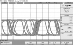
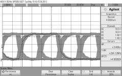
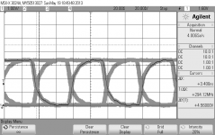
I have attached a couple of measurements, which I made before and after replacing the Toslink devices. The first one is with the original Toslinks, the second one is with a new receiver and the last one is with new receiver and transmitter.
I used infinite persistence and a trigger delay of 20us to get an eye diagram.
Clearly the new receiver improves the signal a lot, but the transmitter also contributes to the clean up.
It is correct that I don't manipulate the external clock at all. I just feed it into the Interface. An output buffer on the ADC/DAC/oscillator can be used here to avoid potential "kick back" (reflections etc.) from the interface cable and input buffer. And the Interface tells the ADC/DAC board to deliver either 22.5792 or 24.576 MHz. See the attached block diagram (V3, V4 and V5 at the bottom of the page).
Attachments
-
 TOSLINK input 192kHz sampling_USBStreamer as source.png16 KB · Views: 322
 -
 TOSLINK input 192kHz sampling_USBStreamer as source_20us trigger delay_new TOSLINK receiver in c.png14.2 KB · Views: 308
 -
 TOSLINK input 192kHz sampling_USBStreamer as source_20us trigger delay_new TOSLINK receiver and .png14.7 KB · Views: 311
 -
USBStreamer Interface V5 Clock Path_131214.pdf18.2 KB · Views: 104
I've had the streamer for months but haven't fired it up. Busy with other things.
I've taken a closer look at things. I'm particularly interested in the TOSLink option to sync to external clock. I'm wondering if the TOSlink input could be used for as an external clock sync for the I2S input. The TOSlink input could be dedicated for this purpose. The TOSlink input must take it's command to change sample rate from it's input signal maybe. If it does then the ADC can be master of everything. Or is the sample rate exclusively controlled by software. There are IC's out there that will do this. The output TOSlink could also be used to detect a sample rate change.
I've taken a closer look at things. I'm particularly interested in the TOSLink option to sync to external clock. I'm wondering if the TOSlink input could be used for as an external clock sync for the I2S input. The TOSlink input could be dedicated for this purpose. The TOSlink input must take it's command to change sample rate from it's input signal maybe. If it does then the ADC can be master of everything. Or is the sample rate exclusively controlled by software. There are IC's out there that will do this. The output TOSlink could also be used to detect a sample rate change.
- Home
- Design & Build
- Equipment & Tools
- QuantAsylum QA400 and QA401