
Hi Mooly, yes the Quads use enequal rails which is achieved by the vitual ground in the driver stages.
The output stage just uses a virtual ground between two series caps.
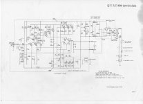
The 606 and 909 are virtually identical.
The output stage just uses a virtual ground between two series caps.
The 606 and 909 are virtually identical.
Attachments
Last edited:
That's right, the output stage is actually AC coupled to the load. Based on that, its a bit open to interpretation what you would call this arrangement.
I'm building a 909 using my rather odd 909 diagram but comparing the values to the 606.
I couldn't get a 82V transformer off the shelf so I've got a 80V 800VA. I did order two of them but I'm wondering if I really need the second transformer ?
I couldn't get a 82V transformer off the shelf so I've got a 80V 800VA. I did order two of them but I'm wondering if I really need the second transformer ?
I would expect all the common "grounds" to be connected in such a way that the main smoothing cap zero volts is common to the active virtual ground.
But maybe not.
Then you can add a few dozen turns to the primary to reduce quiescent current draw and wasteful heating of the transformer. This cuts down saturation, when mains voltage is high.
But maybe not.
if you really need to make adjustments to the supply rail voltages you could add half a dozen turns to the secondary, or maybe two sets of 6 turns so you can adjust in steps.I couldn't get a 82V transformer off the shelf so I've got a 80V 800VA.
Then you can add a few dozen turns to the primary to reduce quiescent current draw and wasteful heating of the transformer. This cuts down saturation, when mains voltage is high.
Last edited:
Two transformers, mono block construction keeping everything separate is possible, one transformer and its not. If 800va isn't enough for domestic use then imo nothing is 😀
It all seems very odd to me. I've got two PSU PCBs each running 15000uF in place of Quads 6800uF, made up of 3 x 4700uF, 12 caps in total.
This thing must have quite an impressive PSSRR ??
This thing must have quite an impressive PSSRR ??
I've never made a study of the Quads tbh but this virtual ground arrangement seems to dictate that the two channels should be kept essentially separate and that will be why two secondaries are shown on this series of amps.
carefully thought out placement of rail decoupling could be very beneficial.It all seems very odd to me. I've got two PSU PCBs each running 15000uF in place of Quads 6800uF, made up of 3 x 4700uF, 12 caps in total.
This thing must have quite an impressive PSSRR ??
But do much transient testing to prove that you have not added ringing instead of attenuating it.
I've never made a study of the Quads tbh but this virtual ground arrangement seems to dictate that the two channels should be kept essentially separate and that will be why two secondaries are shown on this series of amps.
I've ordered two anyway, I've just got to wait 55.46666 (LOL :-( ) days for the second one to arrive. I thought Dad's Aleph 4 was muscle busting but this is going to be heavy.
I would expect all the common "grounds" to be connected in such a way that the main smoothing cap zero volts is common to the active virtual ground.
But maybe not.if you really need to make adjustments to the supply rail voltages you could add half a dozen turns to the secondary, or maybe two sets of 6 turns so you can adjust in steps.
Then you can add a few dozen turns to the primary to reduce quiescent current draw and wasteful heating of the transformer. This cuts down saturation, when mains voltage is high.
It's an odd arrangement, 0V seems to float around a bit. 82V vs 80V seems to be the only difference between the 606, 707 and 909, the rail voltages are slightly different.
It's an odd arrangement, 0V seems to float around a bit.
Not really, its everything else that can move relative to 0 volts... a subtle difference. 0 volts becomes the amplifiers "ground" and is an absolute fixed reference point. Everything moves relative to this point.
To me it just seems odd that 0V is controlled by two such small transistors.
I can understand that is how it seems but the 0v line isn't controlled in that sense. It is a fixed point in the circuit that has been designated 0v and to which all other points are referred. This 0v line has no ability to have current sourced or sunk into it beyond a few milliamps... but it doesn't need to.
I've ordered two anyway, I've just got to wait 55.46666 (LOL :-( ) days for the second one to arrive. I thought Dad's Aleph 4 was muscle busting but this is going to be heavy.
I couldn't have bought a custom made single transformer for that price.
I'm contemplating ordering another lot of MJ15003'S
The only ones from RS are the MJ15003G.
From the data sheet this has a lower gain, is it compatible.
The only ones from RS are the MJ15003G.
From the data sheet this has a lower gain, is it compatible.
G suffix only denotes lead-free tinned leads, nothing to do with the die, case or bonding wires. At least that signifies current production and not yet another shonky clone.
Note the datasheet is still the same as previous with just the appended lead-free status details: http://www.onsemi.com/pub_link/Collateral/MJ15003-D.PDF
Note the datasheet is still the same as previous with just the appended lead-free status details: http://www.onsemi.com/pub_link/Collateral/MJ15003-D.PDF
I bought two dozen MJ15003s from RS a couple of month ago when they reduced the price attractively. Testing at 1 amp their gain range covered 70 to 107 with almost the same number in each decade (with a happy peak at 90-99).
24 is hardly a significant sample but may hint at the RS population.
24 is hardly a significant sample but may hint at the RS population.
This is great, there are so many discrepancies between my 909 schematic and the BOM. I thought I'd bought all the components only to find that the BOM in the service manual is wrong.
- Home
- Amplifiers
- Solid State
- QUAD 909 Clone