Is the function gen. a kit build? Assuming it is and that is a BNC output connector you are patched onto, it suggests a useful 50R impedance for the square waves. Does that outlet provide a sinewave output at 50R too? 'Lucky if it is but then I've come across some oddball old kits or just their designs in recent years, from around the globe.
If the sinewave isn't such a low impedance output (it's usually a nominal 600R unbalanced in a basic generator), it could explain the large discrepancy in measured versus design values, because I don't think the coil impedances should have measured so far off the design values.
If the sinewave isn't such a low impedance output (it's usually a nominal 600R unbalanced in a basic generator), it could explain the large discrepancy in measured versus design values, because I don't think the coil impedances should have measured so far off the design values.
I was watching the output of the generator on one channel of the scope at the same time as looking for the dip on the other channel.
The generator was providing a perfect sine wave at all times.
Don't forget that the calculations were based upon a coil diameter of 10mm, whereas the actual diameter is 11mm, this accounts for the difference in measured value. It's quite startling how the diameter affects the value.
The generator was providing a perfect sine wave at all times.
Don't forget that the calculations were based upon a coil diameter of 10mm, whereas the actual diameter is 11mm, this accounts for the difference in measured value. It's quite startling how the diameter affects the value.
Last edited:
1r0 || 1r0+1r0 || 11r = 0r6286 +-1%, if you use 1% E24 resistors.Even at 50kHz I'm getting silly values for the series resistor to equal Xl.
2 x pi x f x L
1.5uH at 50kHz is 0.47 Ohms
2.0uH at 50kHz is 0.63 Ohms
I don't think this method is going to be practical with such low value chokes.
2*pi*50kHz*2uH = 0.6283ohms
Adjustment to 50020Hz gets the impedance match (+-1%).
Indeed, On Semi have manufactured MJ15003 and all Motorola lines as the OEM since 2000. Anything now branded Motorola should be viewed with suspicion as fakes were around even before Motorola quit their association with making semiconductors. Try a little solvent on the marking, look at the case underside for unexpected marks, wrong diameter lead clearance holes etc.MJ15003 are still commonly available from most suppliers.
Counterfeit Transistors
In my experience, this is one of the top targets for fakes and a lot of effort goes into making them even more convincing as we kindly point out the flaws to the counterfeiters about their previous production. Somehow, the Motorola identity seems to be a better drawcard despite the age discrepancy. I think you'll find there is a limitless supply these "NOS" parts too 😀
Ian, you've put the element of doubt in my mind now.
I've just opened a thread to see how best to test them without cutting them open.
http://www.diyaudio.com/forums/parts/256945-testing-fakes.html#post3942774
I've just opened a thread to see how best to test them without cutting them open.
http://www.diyaudio.com/forums/parts/256945-testing-fakes.html#post3942774
Can anyone think of why Quad used 2 x 2.0uH inductors in series for L2 and L3, other than what might have been commercially available at the time ?
It makes more sense to wind a single 4uH coil on a 10mm former.
It makes more sense to wind a single 4uH coil on a 10mm former.
This inductance only forms a LP stopper for oscillation in the negative side of the output stage. I don't think it needs a precise value, just enough of it. I'd say it was done this way because of parts rationalization and better price breaks for existing stock items, like 0.2 uH. perhaps it also was a convenient way to "fold" the inductor to return the end near to the beginning.
Try out a mock-up of your proposed 4 uH coil and see how it would fit (or not). A 2-layer coil may even be an improvement and fit with room to spare.
Doubling-up has also been done with R29/30 which add to 44R. Being part of the bridge circuit, that dodge could be for precision, at a time when E24 component values were usually quite expensive.
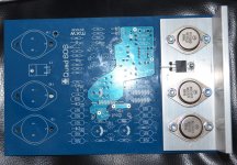
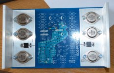
I'm just stuffing my boards and I've come upon a discrepancy.
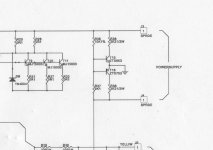
R38 and R39 which form the collector loads of the virtual earth transistors are consistently shown as 2K2 on the 606 and 909 circuit diagrams. However, on the BOM for the 909 they are shown as 3K3.
R36 and R37 which are the potential divider for the same two transistors are constant at 10K and 9K1.
R38 and R39 which form the collector loads of the virtual earth transistors are consistently shown as 2K2 on the 606 and 909 circuit diagrams. However, on the BOM for the 909 they are shown as 3K3.
R36 and R37 which are the potential divider for the same two transistors are constant at 10K and 9K1.
Attachments
Last edited:
I'm guessing here, but as the 909 pushed Vcc up to 116VDC the resistors may have been increased slightly to reduce dissipation in the virtual earth ??
the collector resistors don't do much. I would expect the virtual Earth to work with a very wide tolerance on R38/38 or 9
I think Andrews correct, the resistors simply have to be equal in value, and able to pass "magnitudes more" current than the inherent leakage current of the reservoir caps. So non critical in absolute value. Note that the resistors defining the virtual ground are unequal, presumably to address some non symmetrical clipping behaviour.
- Home
- Amplifiers
- Solid State
- QUAD 909 Clone