There is one manual that seems to refer to Chinese production that also marks a change to modern standard part values. It has no indication of authorship, company details or any normal indications of what series production it refers to: Quad 909 Manual - Stereo Power Amplifier - HiFi Engine
This next schematic is a redrafted official version of the 606/707 but sticks with the original component values: QUAD-909 SCH Service Manual free download, schematics, eeprom, repair info for electronics
Perhaps you have the rest of the service manual and BOM it relates to.
It's a matter of recognizing that Quad as a UK manufacturer of solid state audio components is no more. You need to settle on whether you want a current design or the old 606/707 style that was reworked into the first version 909. Maybe there are clues to the best choice in the OP's posts earlier in the thread?
I'm using the BOMs from this thread, the HiFi Engine Quad Service Manuals and any snippets of information I can find. The OPs schematics are wildly off the ones that I am using.
I'm aiming for a Quad 909 clone with 80V AC supplies.
The inductors are proving to be fun. I've made my own 4.0uH air cored inductors and have bought 2 x 1.5uH and 2 x 22uH ferrite cored ones.
I'm using MJ15003 as the outputs, and, as closely to the original service manual as I can I'm copying the component values for the 909.
Last edited:
Right, well it's the present QUAD 909 manual at HFE that's the problem. It's own BOM and schematic don't match, since the schematic still shows the original 606 part descriptions.I'm using the BOMs from this thread, the HiFi Engine Quad Service Manuals....
I imagine the right way would be to follow the BOM so you have the more recent, and easiest parts to match, incarnation.
That's exactly what I am doing but some components are missing from the 909 parts list ???
It's coming along though.
It's not helped with incorrect component designators on the PCB and duplicate component designators on the schematic.
It's coming along though.
It's not helped with incorrect component designators on the PCB and duplicate component designators on the schematic.
Attachments

The big R15 next to R20 is in fact R26. The true R15 is a smaller resistor next to the Q of the QUAD606. You'll notice I've combined L2 and L3 into a single 4.0uH coil.
Last edited:
Could all the "errors" be deliberately placed in there to make cloning and faking more difficult?
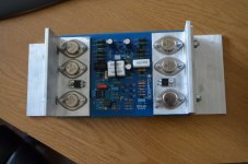
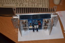
The T03 cans all have insulation on their leads, 5mm lengths of spare wire insulation.

Could all the "errors" be deliberately placed in there to make cloning and faking more difficult?
These are Chinese cloned boards.
I would recommend these boards, if you can live with the error (I've only found that one), they are cheap and are really excellent quality.
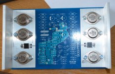
One board fully stuffed - ready for testing.
As the title says, one board is ready for testing.
I'm missing the 1.5uH choke and the mains transformer for the other amp.
As this is fundamentally a Class C amplifier it should be OK to initially power it up without its massive operating heatsink.
Anyone any ideas what sort of idle current I should be looking for ?
Attachments
The finished product will not be fused, relying upon its robust design. However, during test I'd like to keep everything safe.
Any ideas of the rail fuses for the 909 ?
Any ideas of the rail fuses for the 909 ?
As the title says, one board is ready for testing.
I'm missing the 1.5uH choke and the mains transformer for the other amp
So you have done what ? Shorted it out or fitted something like a 0.22ohm ?
As this is fundamentally a Class C amplifier it should be OK to initially power it up without its massive operating heatsink.
Anyone any ideas what sort of idle current I should be looking for ?
If it is Class C you have answered your own question. There is no quiescent current flowing in the outputs... if it is class C.
What about Q7 ?
Mooly, the second amp is unfinished, it will be tested when the final parts arrive. The first amp is complete.
There is a high quality Class A amp in there somewhere, it must be quite small though.
There is a high quality Class A amp in there somewhere, it must be quite small though.
There is a high quality Class A amp in there somewhere, it must be quite small though.
There is. Its Q7, the one that I mentioned.
JLH commented that the 405 had a little bias to improve HD at low levels. The dumpers there are not purely class C. I think D4,5,6 apply a little in the 306,606,707,909 and probably other related models.
Given the heatsink brackets, I don't think you'll have problems that you can't feel and respond to in time anyway.
Given the heatsink brackets, I don't think you'll have problems that you can't feel and respond to in time anyway.
Last edited:
Myself and Quasi came up with nearly identical guidance for supply rail fuses, AFTER the Main Smoothing capacitors.................Any ideas of the rail fuses for the 909 ?
Take the maximum Current that the amplifier delivers into the rated (resistive) load and half it.
The two fuses thus allow the full output current to flow.
eg
100W into 8ohms amplifier.
This is equivalent to 28.28/8= 3.5Aac
Fit a fuse rated at T2A
I use the peak current into the resistive rated load and half it.
i.e. 5Apk becomes a T2.5A fuse in each supply rail.
Quasi and I have posted this information many times in the appropriate Threads.
A word (or more) of caution !
Many amplifiers that lose one supply rail send the output to the still alive supply rail. You need some form of protection if you fit supply rail fuses.
Last edited:
Thanks for all the info about the fuses. After a bit of hunting the 606 schematics help a bit with 6.3A seconadary fuses.
As I'm using 2 x 800VA transformers so I'm not too sure what to use in the mains circuit.
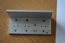
Trying to get it to fit into my chassis with my heatsinks is proving interesting. I don't think these babies get too hot even at full power. Using the heatsinks from both ends rather than from the centre is less than ideal but the heatsink does have a massive 10mm thick base.
As I'm using 2 x 800VA transformers so I'm not too sure what to use in the mains circuit.
Trying to get it to fit into my chassis with my heatsinks is proving interesting. I don't think these babies get too hot even at full power. Using the heatsinks from both ends rather than from the centre is less than ideal but the heatsink does have a massive 10mm thick base.
Attachments
- Home
- Amplifiers
- Solid State
- QUAD 909 Clone