800VA and 240Vac requires a T3.1A fuse for each transformer.
This will require the fitting of a soft start to help the fuse survive the start up current.
This will require the fitting of a soft start to help the fuse survive the start up current.
I thought about soft start but it isn't necessary here as the cap banks are quite small, only 15000uF per transformer secondary.
The soft start is for transformer start up.
Slow charge if you need it is for the smoothing capacitance.
Are you using close rated fuse values?
Or, have you tripled the fuse as is typical for motors and transformers when soft start is not fitted?
I do wish I knew who I am reading, Katie or her Dad? Very confusing having both sharing the same log on.
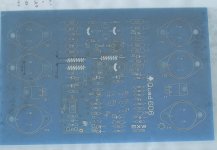
Well, I've just powered up the one amp board and the results aren't as I expected.
I/P is short cct - O/P is open cct.
I've got 30VDC at the output.
Amp is drawing a +ve quiescent current of approx 200mA and there is no magic smoke.
R16 and R17 are a little warm but they are 5W resistors so this could be normal.
I'm wary about trying it with a load resistor in case something fails.
30 volts ? so not rail voltage. Check for oscillation with a scope first to determine whether its a DC problem or not..
It'll be tomorrow before I can get a scope on it, but no it's not rail voltage (+120V with virtual 0V)
Solder 1nF film cap across B-C at ''negative'' row of outputs. One cap for all three. It won't do any harm but oscillation is most probably there around. At least it's been in my case. It might be of some help.
Cheers
Cheers
What sort of current is liable to pass through L2 and L3 ?
In my mind this ought to be the route for the -ve half of the High Power output ?
In my mind this ought to be the route for the -ve half of the High Power output ?
All the current delivered by the dumpers flows in L2 and L3 so 10 to 15 amps peak as a maximum... at a guess. Quiescent should be essentially zero I would have thought.
I've found WHAT but not WHY.
OK. I've hooked up Phil's scope to it and it's not oscillating. The waveform you can see is the ripple from the PSU ~ 100mV Pk-Pk.
What I have found is that +Vcc and -Vcc are NOT EQUAL, one is 40V and the other 80V.
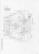
Now, according to the schematic, only the Orange wire, Spkr 0V and Vrt 0V (between the two high voltage ZTXs) should be connected to the connection between the caps on the PSU.
The PCB mimics the original and only the Orange wire is connected to the joint between the caps. The only other wires to the PSU are the Black and the Red (+/- Vcc), other than the AC connections of course. It's a 40-0-40 800VA transformer but the secondaries are wired in series to provide 80VAC across the bridge. Across the caps is indeed about 120VDC.
OK. I've hooked up Phil's scope to it and it's not oscillating. The waveform you can see is the ripple from the PSU ~ 100mV Pk-Pk.
What I have found is that +Vcc and -Vcc are NOT EQUAL, one is 40V and the other 80V.
Now, according to the schematic, only the Orange wire, Spkr 0V and Vrt 0V (between the two high voltage ZTXs) should be connected to the connection between the caps on the PSU.
The PCB mimics the original and only the Orange wire is connected to the joint between the caps. The only other wires to the PSU are the Black and the Red (+/- Vcc), other than the AC connections of course. It's a 40-0-40 800VA transformer but the secondaries are wired in series to provide 80VAC across the bridge. Across the caps is indeed about 120VDC.
Attachments
Last edited:
My L2 / L3 combo were only 0.4mm wire.
Probably not enough for full output current but fine for establishing DC conditions.
It's as though the 0V isn't robust enough ?
Or the amp is drawing an "unbalanced" current from each rail that is outside the range of the virtual earth generator. You need to look at what nodes feed into and out of the virtual ground and check the current flows. Anything "between" the rails can't cause unbalance, its the small currents into and out of "ground" that can if they are large enough.
This morning I tried it with a 10 Ohm load and it makes very little difference, there is still a huge DC imbalance.
This morning I tried it with a 10 Ohm load and it makes very little difference, there is still a huge DC imbalance.
You have to look at all the currents feeding into and out the virtual ground. Unless they are equal there will be an imbalance. The fact that the virtual ground hasn't moved to one or other rail suggests the imbalance is quite small in reality.
Are all the resistors feeding the zeners etc correct. Constant current source LM334 correct.
Have you tried the amp with a signal (on a scope) to see if it otherwise works OK ?
TBH Mooly, I need to clear a space so that I can work on it.
I'm going to carefully check all the component values as there were a few oddities between the schematics and the BOM that I was using.
I'm going to carefully check all the component values as there were a few oddities between the schematics and the BOM that I was using.
- Home
- Amplifiers
- Solid State
- QUAD 909 Clone