I'm planning on 1500Vrms per panel, 2100Vpeak. I have been testing the panels with 500Vrms and I tell you, it is LOUD.
Not sure about the corona detection, I have to look at it if I can keep it in some form or shape.
Jan
Not sure about the corona detection, I have to look at it if I can keep it in some form or shape.
Jan
The corona detection crowbars the audio. Probably even more destructive on a direct drive (not to mention the challenges of implementation across 5 KV). However I'm not sure you could mute the input of the amp and not have a HV peak that could breakdown the gap. The later speakers have a Zener clamp across the audio. I think an MOV array could work better and be even more transparent.
Jan: It a shame there is so much distance between us. I have the HV probes, preamps electrostatic voltmeters etc. current probes you need. Unfortunately its not practical to ship this all over there.
Jan: It a shame there is so much distance between us. I have the HV probes, preamps electrostatic voltmeters etc. current probes you need. Unfortunately its not practical to ship this all over there.
The corona detection crowbars the audio. Probably even more destructive on a direct drive (not to mention the challenges of implementation across 5 KV). However I'm not sure you could mute the input of the amp and not have a HV peak that could breakdown the gap. The later speakers have a Zener clamp across the audio. I think an MOV array could work better and be even more transparent.
Jan: It a shame there is so much distance between us. I have the HV probes, preamps electrostatic voltmeters etc. current probes you need. Unfortunately its not practical to ship this all over there.
Presumably I could use the corona detector output (which basically is a 555 output pulse) to shut things down.
I have been looking at electrostatic voltmeters (the non-contact type Frank) but it's not clear whether they measure DC or AC or both, or whether there are different types for AC and/or DC. There's almost no data on the Trek units to be found.
But I think I can manage without it, just takes more effort and thinking ;-) Actually, getting that 100M probe to work on the AP is much better as it allows processing of the measured data like a freq. or voltage sweep. 100M should be pretty invisible on the HV transformer, compared to the speaker load.
Jan
Last edited:
Last edited:
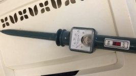
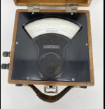
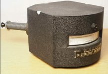
That's a high voltage probe that needs current from the HV. An electrostatic meter sense the electrostatic force and uses no current. You need one to check the bias supplies. I have several- 300V good for condenser mike bias supplies, 5 KV for Quad bias supply and one of the ESH that goes to 30 KV. I have collected these over many years. They are also AC/DC and accurate to 1 MHz. Not that I want to be anywhere near 30 KV at 1 MHz. Here is a little more (but inly a little) Electrostatic voltmeter - Wikipedia
Attachments
That's useful! I was also looking at the 346 and 347.
Some of these have a monitor output useful for signal processing, but they are also very slow, like 25mS to go from 0 to 2kV. But that can be solved in the sweep setup.
Jan
Some of these have a monitor output useful for signal processing, but they are also very slow, like 25mS to go from 0 to 2kV. But that can be solved in the sweep setup.
Jan
To measure HV i always use a resistor devider that's all.. with a current sensor you also could trigger a solid state relay of some kind, no crowbar please as this will destroy the amp. If it is a class D amp just stop the oscillator...
On the HV bias supplies you can get better speaker linearity (supposedly) by increasing the supply impedance. We were using 100Meg resistors on each panel. Obviously to get accuracy you would need 10G input resistance at a minimum. Thats where the electrostatic meters come into play.
The surface charge meters seem pretty common on eBay. Lots of copiers needed them. And they can be pretty cheap. However I can't say of they are useful for measuring a bias supply. And no AC.
The surface charge meters seem pretty common on eBay. Lots of copiers needed them. And they can be pretty cheap. However I can't say of they are useful for measuring a bias supply. And no AC.
I think you can just forget about the ionic detection circuit. This because a dedicated amp will never exceed the voltages of the speaker anyway (if poperly designed). Only with a transformer not knowing what amp will be used this is important...
Jan,
What is the input capacity of your 100Meg probe ?
Even as little as 10pF at 20khz is already 800k, so I wonder if you are better of with this probe than with the 1Meg/1K voltage divider.
Using a 100Meg/10K voltage divider might still be the better solution.
Hans
What is the input capacity of your 100Meg probe ?
Even as little as 10pF at 20khz is already 800k, so I wonder if you are better of with this probe than with the 1Meg/1K voltage divider.
Using a 100Meg/10K voltage divider might still be the better solution.
Hans
Most of the X100 probes I checked were between 2 and 4 pF, which should not be an issue. It would be nice to have a 1Meg input buffer for the probe so its accuracy is not degraded.
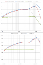
I don’t think the 1Meg load is a particularly significant load for the transformers, and a resistive load should not change the slope of the HF roll-off. Taking the 2nd and 3rd measurements from Post #297 and importing them into Excel using VituixCAD curve tracer, you can overlay them and compute a difference. This is shown in the upper plot of the attachment. You can see there is the expected 0.5-1.0dB decrease from the 1Meg loads, but above 10kHz, there is an abrupt change to a downward -6dB/Oct slope. The lower plot show LTspice results for the same measurements. LF trends have good agreement, but there is no abrupt change at HF.…there must be another reason for the 19dB drop at 20Khz. The 1Meg load places a significant load on your secondary...
It is possible that there is some capacitive loading from the probes (usually ~100pF – 200pF to ground), but since you are measuring across a 1k resistor this doesn’t seem likely. More probable is the possibility of some common mode errors that 1audio mentioned in Post #274, especially with the primary and secondary of the transformers sharing ground runs. Perhaps 1audio can suggest some tests for isolating this contamination.
Attachments
Thanks!ref Baxandall, chapter 3 p 192, Loudspeaker and Headphone Handbook, editor Borewick.

I had actually posted a pic of p192 back in Post #14
I'm a little unclear on what to measure at this point. The current system encompasses the transformer, delay line and panels. I believe the idea is to separate the system between the transformer and the delay line and measure the current with constant voltage at that point. It seems similar to some measurements I have made.
I still have the defective Quad in the shop and if I can get some help lined up I can make a bunch of measurements pretty quickly. Let me think how I can measure both voltage and current at the same time.
I still have the defective Quad in the shop and if I can get some help lined up I can make a bunch of measurements pretty quickly. Let me think how I can measure both voltage and current at the same time.
Jan,
What is the input capacity of your 100Meg probe ?
Even as little as 10pF at 20khz is already 800k, so I wonder if you are better of with this probe than with the 1Meg/1K voltage divider.
Using a 100Meg/10K voltage divider might still be the better solution.
Hans
It is 1/100 of a normal scope input cap which is around 20p I think. It is really extremely low. I'll see if I can do some calculation based on the measured response. But a good point.
Jan
Maybe the easiest way is to replace my 1M/1k attenuator across the xformer by a 10M/1k one. That is low load and very low cap.
The only reason I used a 1M/1k is that I had this very accurate, stable precision attenuator from an old calibrator.
@Demian: I was trying to characterize the required output current over frequency for a direct drive amp. The amp would drive the whole shebang, from the same point where the xformer output is connected. Basically replacing the xformer. If I could measure that at say 500Vrms I can extrapolate to full output voltage.
Jan
Last edited:
I don’t think the 1Meg load is a particularly significant load for the transformers, and a resistive load should not change the slope of the HF roll-off. Taking the 2nd and 3rd measurements from Post #297 and importing them into Excel using VituixCAD curve tracer, you can overlay them and compute a difference. This is shown in the upper plot of the attachment. You can see there is the expected 0.5-1.0dB decrease from the 1Meg loads, but above 10kHz, there is an abrupt change to a downward -6dB/Oct slope. The lower plot show LTspice results for the same measurements. LF trends have good agreement, but there is no abrupt change at HF.
It is possible that there is some capacitive loading from the probes (usually ~100pF – 200pF to ground), but since you are measuring across a 1k resistor this doesn’t seem likely. More probable is the possibility of some common mode errors that 1audio mentioned in Post #274, especially with the primary and secondary of the transformers sharing ground runs. Perhaps 1audio can suggest some tests for isolating this contamination.
Hi Steve,
Nice analysis with the 6dB roll off.
You get the same ca. 8dB@20Khz in current difference between the two curves as I got in post #305.
I cannot think of any way how this can happen with such a sharp transition.
Hans
Last edited:
Jan,
I suppose you are measuring the secondary voltage of just one transformer, so between gnd and hot.
What voltage do you measure when connecting to the other transformer ?
Hans
I suppose you are measuring the secondary voltage of just one transformer, so between gnd and hot.
What voltage do you measure when connecting to the other transformer ?
Hans
- Home
- Loudspeakers
- Planars & Exotics
- QUAD 63 (and later) Delay Line Inductors