My other issue with the frontro is the 800 Hz crossover. Even if absolutely wonderful above 800 Hz getting a good transition at that frequency is really hard and in this case the woofer is destined to be too far from the mid-tweeter really limiting the area where they blend well.
Convinced of what?...I still have this little voice in the back of my head that tries to tell me that I'm not yet convinced
BTW, I recently re-read Walker's 1979 AES presentation and noticed 2 comments(one at the beginning, one at the end) that have direct bearing on topics of the usability and patent-ability of the virtual point source concept the ESL-63 is based on.
"This idea was in fact suggested over 50 years ago, so why was it not used and where does it go wrong? If this was all we did, the final reproduction would not be quite correct. First, with a membrane of about 90cm diameter, the output would fall by about 3dB/oct below 300Hz. This is because the size of the membrane is smaller than the total wave front created by our imaginary pulsating sound source and so not so much air is vibrated. Above about 300Hz, undulations of about 6dB to 8dB would appear in the frequency response because of the discontinuities caused by the finite size of the membrane."
"So finally, what is new about all this? Really, it is a lot of old ideas fitted together. Kellogg in 1929 proposed the connection of a series of electrostatic elements by inductors as a delay line. Shorter of the BBC took out a patent in 1941 describing the connection of a series of annular rings, and Janszen in 1953 suggested variations on the same theme. All I have done is to collect all these ideas and add a little work which says that if you can make the device acoustically transparent, then the performance can be predicted."
Reading the company literature I infer that smaller size was a prime motivator for its design, and that generally comes with compromises as you point out. As such, I don't think the FrontRo was intended to be a direct competitor to the Quads. I'm personally not so much interested in the FrontRo as I am in the concept used for the ESL portion of its design.My other issue with the frontro is the 800 Hz crossover. Even if absolutely wonderful above 800 Hz getting a good transition at that frequency is really hard and in this case the woofer is destined to be too far from the mid-tweeter really limiting the area where they blend well.
+1 !!!... Walker had a really quite incredible computer: his name was Peter Baxandall.
Anybody who has read Baxandall's writings can't help but come away in awe of his ability to see both forest and trees, managing to simply and clearly explain how things all fit together. It seems I learn something new every time I re-read his ESL paper. He was a truly gifted man.
SteveConvinced of what?
The explanation that was used, was somewhat confusing for a dumbo like me.
But at the end I got the message in a way that worked for me.
One can take a constant time delay between rings, such as used for the first 5 ESL63 rings.
You can also also take fixed geometrical steps sizes between the rings, as also used by Quad.
But you can't use both things at the same time when you are aiming for the best possible polar diagrams with large electrostats such as the ESL63.
1) You should either use a fixed geometrical step size for the rings and use variable delay between rings of [b-sqrt(b^2-y^2)].
When using a fixed timestep per ring in this situation, the delay will fit the first ring (delay=0) and may be right for only one of the other rings, but the rest will have a wrong delay.
2) However you could also use a fixed time delay step per ring, but then you have to arrange the rings in variable distance steps.
So this is what I think what the patent was telling.
Now looking back at the ESL63, the geometrical layout can't be changed, so the only way to make a step in the direction of getting an even nicer polar diagram for the higher frequencies, is to reorganise the whole delay line section.
That could be done, but will be quite some job, at least needing individually differing delay line inductors per ring.
I don't think anyone is waiting for this kind of "tuning", but at least for me, it was more the technical challenge to understand the differences between the two concepts and that IMO the ESL63 can theoretically also be modified into a "pulsating sphere" .
Hans
Hans Polak. Have you read the chapter by Baxandall in loudspeaker handbook where the ESL 63 is described?
Hans Polak.
Have you read the chapter by Baxandall in loudspeaker handbook where the ESL 63 is described?
I would love to, but I don't have this book.
Hans
I would love to, but I don't have this book.
Hans
Loudspeaker and Headphone Handbook - Google Books
now you do. 🙂
Hans
have you any idea why Quad chose the ring spacing they did, this must have been be design as changing them at the design stage would be trivial
Stuart
have you any idea why Quad chose the ring spacing they did, this must have been be design as changing them at the design stage would be trivial
Stuart
It´s explained in the book linked above....
I have got many good ideas from this book.
One example is to grind of 1mm from the middle panels to increase the capacitance. And by that achieve higher efficiency and proportional less stray capacitances.
And then drive them active as I do today, with a cutoff LR24dB at approx 120-150 Hz.
And then use RePhase to straight out the frequency response and phase response...
Or use Dirac maybe.
Wow, thank you so much.
I'll read it with great attention.
Hans
Read page 192 and the meaning that starts with "Arriving at a..." and you will start to smile, if you know that Baxandall, Walker, and some more engineers spent 18 years (from 1963 to 1981) until this baby reached the market, adding many years in the 50 ties as well with experimenting on electrostatics, it´s even getting fun!
There is another piece of magic in the ESL 63 that has not been mentioned, yet.
Walkers equation, which relates the far-field SPL to the stator current, shows that the stator current should be the same at all frequencies (for the same input voltage) to give a flat frequency response. This is not possible with the normal unsegmented ESL which is almost a pure capacitor, unless you include modify the frequency response of the amplifier.
By segmenting the ESL and connecting the capacitive segments with inductors, he converted the ESL to an LC transmission line which behaves as a pure resistance, and now the stator current is the same for all frequencies, and you can use any audio amp without the need for special equalisation circuitry. Check wikipedia entry for transmission line - and see the characteristic impedance entry.
Mellows solution with the oscillating sphere (as opposed to walkers pulsating sphere or point source) does not have a flat response - it has a rising response at high frequencies. I've not checked the detail, but maybe Mellow uses that lift to compensate for falling SPL due to stators and membrane.
The total current feeding a lossless, terminated LC transmission line is the same for all frequencies, but the current thru each of the ring segment capacitance still increases proportional to frequency. The current thru the termination impedance must be added together with the sum of all the segment currents to get the frequency independent input current. As described in Section 3.4.2 of the Baxandall ESL chapter, the ESL-63 adds segment 7 (and 8 really) as part of the termination impedance to recover the portion of the total current required to get a flat response.…By segmenting the ESL and connecting the capacitive segments with inductors, he converted the ESL to an LC transmission line which behaves as a pure resistance, and now the stator current is the same for all frequencies, and you can use any audio amp without the need for special equalisation circuitry. Check wikipedia entry for transmission line - and see the characteristic impedance entry.
The attached LTspice simulations illustrate.(Values for L & C chosen to simplify math)
Attachment #1: The total current into the transmission line is I(R1) and is seen to be flat with frequency(ignoring the wiggles at the upper end due to descretization of the TL). The sum of the currents thru the ESL segment capacitances I(R2) is seen to increase with frequency. Add the current from the termination resistance I(R3) to the segment currents and you get the flat total current. But the far-field response is only due to current in the segment capacitances, so is not flat but increases with frequency.
Attachment #1: Inserting additional ESL stator area (C7) in series with the termination resistance and the response is flattened down to frequency where the termination impedance starts to increase because of the capacitance of the inserted stator area. This is in essence what is being down with segments 7 & 8 on the ESL-63. The tricky part is that the TL in the ESL-63 is not lossless and includes additional capacitive load per TL section from the compensation capacitors, so an additional shunt capacitance component C13 is used to help equalize the currents flowing thru the termination segments to match the sum of the currents in the ring segments to produce a flat response. The Walker equation relationship between stator current and far field pressure response made it possible to work out a compensation scheme for the real-world circuit with all its losses and parasitic components without lifting a microphone.
The currents in all segments of a theoretical virtual oscillating sphere are all the same and increase proportional to frequency. However, the delay between segments is not constant as per the ESL-63, but increase with ring number. This increasing delay results in flat response at high frequencies, just like a real physical oscillating sphere, on-axis and for all off-axis angles as well. If needed, I can provide LTspice results this weekend to show plots similar to those attached for the ESL-63 to illustrate.Mellows solution with the oscillating sphere (as opposed to walkers pulsating sphere or point source) does not have a flat response - it has a rising response at high frequencies. I've not checked the detail, but maybe Mellow uses that lift to compensate for falling SPL due to stators and membrane.
Attachments
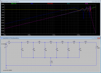

Here is an initial LTSpice model that I have made for the FrontRo ESL.
I have used 3mm gaps between the rings, to prevent a short circuit between them.
The delay lines I have inserted are without any of the Rser, Rpar and Cpar that I used for the ESL63.
Two models were simulated, the one at the left direct driven without step up transformer and in the simulation to the right the EL63 transformers are used.
For both situations I have shown the currents through the membranes Rn0 to Rn6 and also the voltages over these 7 elements.
Hans
Attachments
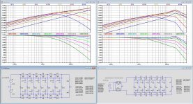
I was surprised with the immensely small membrane capacitances, starting at 0.57pF for the centre ring, which is almost impossible to achieve with the wiring leading to this element, but it turned out that I had made a factor 10 mistake for all capacitances.
But even then, 5.7pF will still be hard to achieve for the first membrane plus wiring.
Fortunately with LTSpice it's almost a hit of a button to correct the error.
So here are the newly calculated currents and voltages for the membranes in the first image below.
Sorry for the earlier mistake.
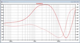
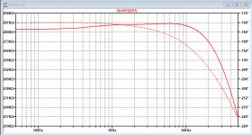
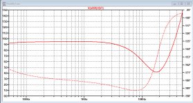
The impedance curve is nice flat without the step up transformer in the second image.
With the step up transformer from the ESL63 a 4 Ohm dip shortly before 20kHz is created meaning that this is probably not the right Xformer for the job, see third image below.
The turnover frequency in the Mellow paper fits quite well for the turnover frequency f1, but all the others are up to 35% lower.
I checked whether this had to do with the 3mm gap between the rings that I have used, but this hardly has any effect on the turnover frequencies.
One last thing: the terminologies pulsating versus oscillating spheres are still confusing me. Can somebody explain what's behind these words.
Hans
But even then, 5.7pF will still be hard to achieve for the first membrane plus wiring.
Fortunately with LTSpice it's almost a hit of a button to correct the error.
So here are the newly calculated currents and voltages for the membranes in the first image below.
Sorry for the earlier mistake.
The impedance curve is nice flat without the step up transformer in the second image.
With the step up transformer from the ESL63 a 4 Ohm dip shortly before 20kHz is created meaning that this is probably not the right Xformer for the job, see third image below.
The turnover frequency in the Mellow paper fits quite well for the turnover frequency f1, but all the others are up to 35% lower.
I checked whether this had to do with the 3mm gap between the rings that I have used, but this hardly has any effect on the turnover frequencies.
One last thing: the terminologies pulsating versus oscillating spheres are still confusing me. Can somebody explain what's behind these words.
Hans
Attachments

Think of a pulsating sphere as a sphere whose diameter increases and decreases at an audio rate....the terminologies pulsating versus oscillating spheres are still confusing me.
Think of an oscillating sphere as a sphere of fixed diameter that shakes back and forth at an audio rate.
Attachments
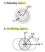
Think of a pulsating sphere as a sphere whose diameter increases and decreases at an audio rate.
Think of an oscillating sphere as a sphere of fixed diameter that shakes back and forth at an audio rate.
O.k., got it, but does this apply to any of both systems or is it more of a commercial statement to keep them apart ?
Seeing the ESL63 as an pulsating sphere is not the first thing that comes to my mind.
Hans
Steve,Inserting additional ESL stator area (C7) in series with the termination resistance and the response is flattened down to frequency where the termination impedance starts to increase because of the capacitance of the inserted stator area. This is in essence what is being down with segments 7 & 8 on the ESL-63. The tricky part is that the TL in the ESL-63 is not lossless and includes additional capacitive load per TL section from the compensation capacitors, so an additional shunt capacitance component C13 is used to help equalize the currents flowing thru the termination segments to match the sum of the currents in the ring segments to produce a flat response. The Walker equation relationship between stator current and far field pressure response made it possible to work out a compensation scheme for the real-world circuit with all its losses and parasitic components without lifting a microphone.
Thanks for your explanation.
The deeper you dive in the ESL63 details, the greater the mystery how they got things done in those days.
What a fantastic achievement.
Hans
- Home
- Loudspeakers
- Planars & Exotics
- QUAD 63 (and later) Delay Line Inductors