Hi Sheldon,For the record, I've NEVER advocated removing the input network. It makes a measurable difference, and now you can see that the model also confirms it.
Quad not changing the delay lines for the extra two panels is classic Quad these days. It appears that they have zero engineering people working on the guts of the speaker. The panels are identical, the clamp circuit is identical, the HV power supply is identical and the input and delay lines are identical to the latest ESL-63 design. The only change they made was to ad a weird transistor circuit to drive the LED logo on the front.
In fact the resistor for the power LED is running at its power limit, and for a LOT of years (until the 2805 mid production I believe) they had a 16V filter cap in the low voltage power supply, and that supply runs at or slightly above 16v in the USA.
It would be very interesting to see how two extra bass panels changes the speaker response.
Sheldon
I will run the sim with the extra panels and see what it brings.
Hans
The extra panels gives a big hump as seen in stereophile measurement:
It´s however easy to double the R6 and R8 as i mentioned before and flatten out the response.
MT-Audio and me did a lot of testing and measurements on this 15 years ago.
Also R5 and R7 can be increased to reduce the "beaming" and the extreme small sweet spot.
Those resistors is placed after the important R3 R4 C13, which is a termination of the delay transmission line.
Attachments
Adding two extra bass panels changes remarkably little to the signals on the inner six rings.
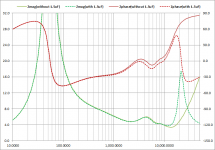
In the first picture below, you see resp. the electrical signal on ring # 6, 7 and 8 without and with the extra 2 bass panels.
The first 5 rings do not show any difference and are omitted.
Ring #6 shows only a very minor drop of 0.2dB between 100Hz and 300Hz, which will very unlikely lead to a noticeable difference in sound.
The first bass panel #7 however drops 1.8dB around 300Hz, which seems a lot.
The bass panels in ring #8 do drop from zero dB at Lf to 4dB at Hf.
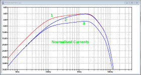
According to Peter Walker's formula, power/m2 is directly proportional to the current flowing through the panel, so in the second image I have shown these currents to give a better view on the situation.
Three curves are visible.
1: current with added bass panels
2: current without added bass panels
3: current through the original bass panels when the extra bass panels are added.
From these curves one can see that above 1kHz the same amount of power is produced with and without the added panels.
The diminished power radiated by the original bass panels is corrected to the original level by the two added panels
Going down in frequency from 1kHz, up to ca 6dB more, or twice the power is produced, which is partly corrected by the lesser output of ring #7, so most of the added bass seems to be produced below 100Hz.
Hans
In the first picture below, you see resp. the electrical signal on ring # 6, 7 and 8 without and with the extra 2 bass panels.
The first 5 rings do not show any difference and are omitted.
Ring #6 shows only a very minor drop of 0.2dB between 100Hz and 300Hz, which will very unlikely lead to a noticeable difference in sound.
The first bass panel #7 however drops 1.8dB around 300Hz, which seems a lot.
The bass panels in ring #8 do drop from zero dB at Lf to 4dB at Hf.
According to Peter Walker's formula, power/m2 is directly proportional to the current flowing through the panel, so in the second image I have shown these currents to give a better view on the situation.
Three curves are visible.
1: current with added bass panels
2: current without added bass panels
3: current through the original bass panels when the extra bass panels are added.
From these curves one can see that above 1kHz the same amount of power is produced with and without the added panels.
The diminished power radiated by the original bass panels is corrected to the original level by the two added panels
Going down in frequency from 1kHz, up to ca 6dB more, or twice the power is produced, which is partly corrected by the lesser output of ring #7, so most of the added bass seems to be produced below 100Hz.
Hans
Attachments

The extra panels gives a big hump as seen in stereophile measurement:
It´s however easy to double the R6 and R8 as i mentioned before and flatten out the response.
MT-Audio and me did a lot of testing and measurements on this 15 years ago.
Also R5 and R7 can be increased to reduce the "beaming" and the extreme small sweet spot.
Those resistors is placed after the important R3 R4 C13, which is a termination of the delay transmission line.
Thanks for that info, it would make sense to change the R's in the simple RC filter to keep the corner frequency the same with the doubling of the panel capacitance.
I don't have a lot of faith in Stereophile's measurements. You can see by that measurement in the high frequencies that they are not on axis with the speaker, or they have an issue with their measurement setup at the high frequencies. Getting that low frequency response right can be quite tricky unless they are in a very large space or outside.
Sheldon
The extra panels gives a big hump as seen in stereophile measurement:
It´s however easy to double the R6 and R8 as i mentioned before and flatten out the response.
MT-Audio and me did a lot of testing and measurements on this 15 years ago.
Also R5 and R7 can be increased to reduce the "beaming" and the extreme small sweet spot.
Those resistors is placed after the important R3 R4 C13, which is a termination of the delay transmission line.
Your shown recording coincides relatively well with my findings.
When doubling the value of R6 / R8, the current will be halved at LF but will also cause a loss of power around the sensitive area of 1kHz.
At the end this seems a step back to a system with only 2 bass panels.
This needs a more sophisticated approach as what’s has been done by simply adding two extra panels.
Hans
Hans, you can calculate how much of the energy that passes trough R3 R4 C13 and you will see that most of the audio power is lost in this circuit....
The current will be dissipated as heat in R3 R4 but also in the delay coils resistive part.
I have been thinking a lot on how to tap that energy (current) out and i have tried to filter out the low frequency part of this "short circuit" and feed it to some extra bass panels.
But no luck so far, i tried to lower C13 and add bass panels with extra resistance in series instead. But the problem is that you have to keep the impedance exactly right! This termination is crucial for the delay line and the signal to the rings to stay clean from reflections that is occurring at the end of the delay line.
We could come up with something with your model 🙂 i mean its really sad to have a nice expensive power amplifier and just convert the music it to heat... but actually, that whats happening in ordinary voice coils.
Last edited:
I was interested in how the delay line was terminated as I want to add 4 extra bass panels but I did wonder about building a second speaker with just the 4 bass panels and the audio transformers and using an electronic delay to match the delays and a digital crossover to drive the extra panels, I have all the necessary parts including a pair of 909s to drive everything but I have not yet had the time
Stuart
Stuart
Its not so simple since the added bass panels will need to be balanced in level. i suspect they tend to have less output each but more as a composite when added. it should be easy to see what happens to the delay line with the added capacitance. Also the voltage across the panels is not directly representative of the acoustic output of the panels. That would be far too easy.
RE power- look at the phase angle of the voltage-current relationship to understand the power dissipation. With the sim lots of otherwise difficult analysis is easy to do.
I agree that it seems the engineering behind the speakers left years ago. The last significant change was the zener clamp boards, something I don't find to be the best solution for the problem. The rest is really window dressing. By now the speakers should have integrated amps and dsp. A few other tweaks and they could be really remarkable and current beyond audiophile circles.
Place them 90 degree like the founder of SME did. I can not find the picture but on recommendation from Peter Walker he placed a double set of ESL-63 at the same height, side to side and 90degrees angled. One speaker facing forward and the other facing sideways. Yes he had a gigantic room!
You can also add some wings. if you do the calculation you will see that if you double the pathway from front to back you will increase the output in the bass with 6dB!
Or if you go double Quad ESL63 and by that double the pathway, (one pair could be driven fullrange facing forward, and the other one working from 300Hzand down) you will both get the benefit of pathway amplification AND the double surface area. I guess you theoretical will end up with 12dB increase in output in the low frequencies. But you need to increase the height as well, and make the speakers air tight towards the floor as well.
Attachments

Hi Demian,Its not so simple since the added bass panels will need to be balanced in level. i suspect they tend to have less output each but more as a composite when added. it should be easy to see what happens to the delay line with the added capacitance. Also the voltage across the panels is not directly representative of the acoustic output of the panels. That would be far too easy.
RE power- look at the phase angle of the voltage-current relationship to understand the power dissipation. With the sim lots of otherwise difficult analysis is easy to do.
I agree that it seems the engineering behind the speakers left years ago. The last significant change was the zener clamp boards, something I don't find to be the best solution for the problem. The rest is really window dressing. By now the speakers should have integrated amps and dsp. A few other tweaks and they could be really remarkable and current beyond audiophile circles.
The more I simulate the ESL with extra bass panels, the more I get convinced that the ESL63 is a well balanced system, where you cannot simply add a few bass panels.
The idea is of course to extend the FR range in the bass range.
With a larger surface, capacitance is lower so the -3dB point also lowers.
But not only that, but the drive current that's flowing because of the used topology also increases and so does the SPL of the bass panels, thereby completely ruining the tonal balance, because it's the current that is direct proportional to SPL and not the voltage
So my advice would be to add a second frame with 4 bass panels, driven from two amps with a crossover filter between them.
That's the best way to get a flat FR.
One thing to solve is yet to lower the resonance of the panels, currently at 50Hz, which helps to lower the FR in the ESL63 but that should be lowered when using more panels.
Hans
I think it may be not too useful to add panels since the panels have an acoustic resonance around 50-60 Hz. More panels may make that more obvious and I suspect the output will drop significantly below that resonance. Adding 2 panels (969?) gets you 3 dB more max output (bately audible) with lots of effort. Controlling the rear wave will do more for a lot less effort.
I would use a subwoofer (notwithstanding that I made and sold subs for '63s for a number of years) but integration is not trivial and a typical resonant sub tends to be quite obvious with Quads. Again modern DSP tools make such a project likely to be more successful.
I would use a subwoofer (notwithstanding that I made and sold subs for '63s for a number of years) but integration is not trivial and a typical resonant sub tends to be quite obvious with Quads. Again modern DSP tools make such a project likely to be more successful.
Hi Demian,
The more I simulate the ESL with extra bass panels, the more I get convinced that the ESL63 is a well balanced system, where you cannot simply add a few bass panels.
Are you implying the the great Quad would just slap dash add a couple bass panels and do nothing else and then laugh all the way to the bank?! I'm shocked.
For example in the 989, they didn't stiffen the internal rails that hold the panels when they added two more panels to the stack, which makes the rail system much less rigid than it was with 4 panels and allows much more deflection. This means that the panels can now hit the dust covers and the insides of the grilles and damage the dust covers in shipping.
They seemed to have learned the lesson in the 2905s and later.
Sheldon
With its location on the schematic adjacent to the limiter circuit, I had assumed its purpose was to smooth out the limiter action. Looking at the phase of the impedance above 20kHz, it might also have been added to keep the phase of the impedance in check above 20kHz to make the speaker a more friendly load for stability challenged amplifiersThe only visible effect of the 1.5uF at the input network is the impedance peak slightly above 20kHz. On the FR it has hardly any visible effect.
Attachments
The extra panels gives a big hump as seen in stereophile measurement
I wonder if that measurement is correct, it may just be the proximity effect. The graph says that they plotted the near field response below 300 Hz, which is where you see the hump, but a flat-panel ESL designed for a flat far-field response has a -20 dB/decade slope in the near field.
I wonder if that measurement is correct, it may just be the proximity effect. The graph says that they plotted the near field response below 300 Hz, which is where you see the hump, but a flat-panel ESL designed for a flat far-field response has a -20 dB/decade slope in the near field.
This is how Stereophile measures speakers.
Measuring Loudspeakers, Part Three Page 8 | Stereophile.com
Hans
I wonder if that measurement is correct, it may just be the proximity effect. The graph says that they plotted the near field response below 300 Hz, which is where you see the hump, but a flat-panel ESL designed for a flat far-field response has a -20 dB/decade slope in the near field.
And the data above that 300hz point is averaged over 30deg. Averaged with what weighting?
I stick by my earlier postulation that Stereophile measurements are worthless.
Sheldon
David Berriman at HiFi World did this measurement and it follows my reasoning that you get both an amplification from the larger pathway and boost from the panels. However the leakage out from the sides can be reduced by "wings".
Electrically you increase R6 and R8 to 720kOhms. Have tried this and this works very good. Deep punchy bass, totally free from distortion and coloration.
Total SPL is not getting better though, thats why i use active crossover to get 10dB more dynamics. Greater power handling.
Electrically you increase R6 and R8 to 720kOhms. Have tried this and this works very good. Deep punchy bass, totally free from distortion and coloration.
Total SPL is not getting better though, thats why i use active crossover to get 10dB more dynamics. Greater power handling.
Attachments
And the data above that 300hz point is averaged over 30deg. Averaged with what weighting?
Sheldon
I don't think there is any weighting involved.
There was a serious caveat in the original ESL-989 review regarding the near measurements. They are usually very good at warning readers that large speakers present problems for them and that their standard quasi-anechoic methods do not accurately reflect in-room response for large speakers at greater distances. They are trying to maintain consistency across reviews though, so present the standard data set.
In a later review, Atkinson showed the in-room response, which is much flatter.
Measuring Loudspeakers, Part Three Page 3 | Stereophile.com
"The curve is actually a composite, consisting of the seven spatially averaged responses taken with a 30kHz bandwidth from 1kHz to 30kHz, a separate on-axis measurement taken with a 5kHz bandwidth from 312.5Hz to 1kHz (this makes the graph look more presentable, but the true frequency resolution is unchanged), and the complex sum of the speaker's nearfield port and woofer responses below 312.5Hz"
Quad ESL-989 electrostatic loudspeaker Measurements | Stereophile.com
"Interpreting the measured frequency response of a fairly large panel speaker like the ESL-989 is not straightforward. First, the assumption that the microphone is in the speaker's farfield at my routine 50" distance is no longer true, which means that there will be a slight downward trend with frequency, due to the proximity effect. Second, my usual nearfield measurement of the low frequencies will not show the effect of the dipole cancellation, as the antiphase backwave increasingly wraps around to cancel the speaker's direct output with decreasing frequency. The peaked-up bass shown in fig.2 will therefore tend to be more flat in the farfield than it appears in this graph"
Quad ESL-989 electrostatic loudspeaker John Atkinson May 2003 | Stereophile.com
Attachments

David Berriman at HiFi World did this measurement and it follows my reasoning that you get both an amplification from the larger pathway and boost from the panels. However the leakage out from the sides can be reduced by "wings".
The diaphragm is acoustically transparent, so why does a larger diaphragm result in a larger pathway? Isn't it essentially zero with an acoustically transparent diaphragm, no matter how large the diaphragm may be?
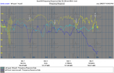
Some Quad measurements
First are two measurements at two different distances and then a windowed measurement same location with the first arrival windowed out to see the energy bouncing around the room. These are not smoothed and pretty high resolution so much messier than the usual published plots
They all show significant energy below 50 Hz but that may even be ambient noise.
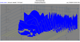
The second is a waterfall from the same location.
The quad is not stock, but a Crosby mod so different dust covers, grill, caps in the delay line etc.
First are two measurements at two different distances and then a windowed measurement same location with the first arrival windowed out to see the energy bouncing around the room. These are not smoothed and pretty high resolution so much messier than the usual published plots
They all show significant energy below 50 Hz but that may even be ambient noise.
The second is a waterfall from the same location.
The quad is not stock, but a Crosby mod so different dust covers, grill, caps in the delay line etc.
Attachments
- Home
- Loudspeakers
- Planars & Exotics
- QUAD 63 (and later) Delay Line Inductors