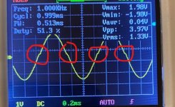
I've set the volume on the preamp so the scope says Vmax=2V, Vmin=-2V while playing the 1KHz tone.
Good channel: https://i.imgur.com/0ZUvlyZ.jpg
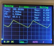
Ah, yeah the sawtooth/tri wave doesn't alter when I change the volume of the test tone. Also, it shows as 100Hz on the scope, so this must be from something else.
Bad channel: https://i.imgur.com/TtyG5TG.jpg
Thank you for all your help today! Much appreciated.
Good channel: https://i.imgur.com/0ZUvlyZ.jpg
Ah, yeah the sawtooth/tri wave doesn't alter when I change the volume of the test tone. Also, it shows as 100Hz on the scope, so this must be from something else.
Bad channel: https://i.imgur.com/TtyG5TG.jpg
Thank you for all your help today! Much appreciated.
So two unexpected results there.
The 'good' channel. Was a load connected for that one? Not that it matters because there looks like an issue here whether it did or did not, but if not then it is is even more odd.
So the first image has what looks like classic crossover distortion visible which is bizarre for an amp like the Quad. I would check on this one that the input signal is clean. Set the amp up as it is now and then look at the input.
Could it be a measurement aberration very odd.
Do you see a clean sine or has it got those glitches?
Second image shows ripple from the rails. Classic sawtooth shape wave. It is 100Hz because of the action of the bridge rectifier. 50Hz mains gives 100Hz ripple. So this shows a major problem with this channel.
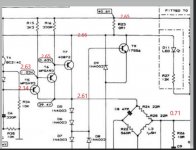
I would begin by checking basic DC conditions first for that one even if you have already quickly measured a few things... and just looking at the service manuals and some of the quoted voltages are totally wrong. I've crossed those out. The others look correct.
The 'good' channel. Was a load connected for that one? Not that it matters because there looks like an issue here whether it did or did not, but if not then it is is even more odd.
So the first image has what looks like classic crossover distortion visible which is bizarre for an amp like the Quad. I would check on this one that the input signal is clean. Set the amp up as it is now and then look at the input.
Could it be a measurement aberration very odd.
Do you see a clean sine or has it got those glitches?
Second image shows ripple from the rails. Classic sawtooth shape wave. It is 100Hz because of the action of the bridge rectifier. 50Hz mains gives 100Hz ripple. So this shows a major problem with this channel.
I would begin by checking basic DC conditions first for that one even if you have already quickly measured a few things... and just looking at the service manuals and some of the quoted voltages are totally wrong. I've crossed those out. The others look correct.
Attachments

I've just bought a Telequipment D755 scope, which I'll hopefully be picking up today. The cheap one I was using was a bit of a pain to use, and a lot of the areas I probed I couldn't get the waveform onto the screen at all. The 'new' one was only £30, so a bit of a steal, I think. I'll recreate those results again later.
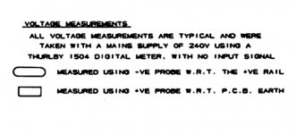
I think those results you crossed out might actually be correct, as I got those results pretty much exactly. The ones you've circled are in square boxes, and the key in the bottom right corner says square boxes are measured with +ve probe with respect to PCB earth, and the ones in rounded boxes are measured with -ve w.r.t the +ve rail. I will check these again, though. And I'll get back to you later when I have the new scope. Thanks.
I think those results you crossed out might actually be correct, as I got those results pretty much exactly. The ones you've circled are in square boxes, and the key in the bottom right corner says square boxes are measured with +ve probe with respect to PCB earth, and the ones in rounded boxes are measured with -ve w.r.t the +ve rail. I will check these again, though. And I'll get back to you later when I have the new scope. Thanks.
Oh, I forgot to mention that I did have a load connected for those scope results. An 8 ohm 100W resistor across each output set.
The scope sounds good 
Just looking at those voltages... here is my reasoning 🙂
Positive supply voltage of 0.6 volts right at the top. It looks like +0.6 but zooming in and it could be a 40. I'll concede that one 😉
R23 is 0.1 ohm and will have the same +40 volts on each end. T7 is shown as +0.6 volts on the base and having +40 on the emitter. Not possible. The base should be around 0.6 volts more negative than the emitter, so around +39.6 on based on +40 volt rail.
The same errors carry through T5 and T6. Each base voltage should be around 0.6 volts more negative than the emitter (because they are all PNP's).
These would be what I would expect.
Attachments
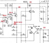
Ah, ok. I must have forgotten to take the measurement at the top, because on the right (good) channel it's 40.8V and on the left, it's 2.67V. The two at T7 are about the same at 2.66V. If I measure the screw of T7 (which I think is the collector?), it's 2.63V.
I'm just popping out to collect the scope, and when I'm back ill check more of those voltages!
I'm just popping out to collect the scope, and when I'm back ill check more of those voltages!
40v sounds right (its the positive rail) so 2.6 on the other channel sounds like a problem somewhere.
Recheck them all methodically working from the top rail downwards.
Recheck them all methodically working from the top rail downwards.
Here are the voltages for the left channel: https://i.imgur.com/uBixBHs.png
The ones for the right channel were ok, and the one which you said should be near zero is 1.3v on the right.
But just to check, did you intend for me to measure these with black lead from the meter on the pcb/chassis earth? Because when I measure the voltages in the ovals with one lead on the +ve rail like the key says, I get the same results that are on the schematic.
Where you measure from makes a massive difference.
I was thinking you were measuring from the ground point which is the junction of the two reservoir caps so that was where I intended them to be measured from.
Deleting what I typed it is to confusing 🙂
Stick to fault finding it the conventional way and see where it falls down.
I was thinking you were measuring from the ground point which is the junction of the two reservoir caps so that was where I intended them to be measured from.
Deleting what I typed it is to confusing 🙂
Stick to fault finding it the conventional way and see where it falls down.
Attachments
Yeah, they've made it quite confusing, haven't they?
The measurements on the photo I just posted were measured from ground.
The measurements on the photo I just posted were measured from ground.
They sure have.
The 'picture' I have is this one you posted. I'll have to look in more detail at the service manual because it seems the power supply is not shared between channels, they are separate as far as a quick look seems to show.
The voltage across the two reservoir caps in each channel should be equal with the centre point forming the virtual ground for that channel.
If one channel has a fault the 50:50 ratio in voltage across those caps could shift, particularly if speakers are connected.
The total voltage of the two caps should add up to the full rail voltage which looks to be around 75 to 80 volts DC.
So at this stage for comparing you have to treat each channel as a separate item.
I'll try and have a closer look tomorrow although it could get to later in the week as I've a bit on with other stuff at the moment.
Attachments
I just checked the caps C10 and C11 again and I think it has changed drastically again. On the right, C10=40.2V C11=37.8. On the left, C10=2.6 and C11=75.2, so it looks like C11 is taking most of the rail.
Please, take your time, and thank you so much for your help so far.
Please, take your time, and thank you so much for your help so far.
I'm getting 59V AC out of the transformer just before the bridge rectifier (D12) on both channels, but also -66V total DC on the bad channel.
The bridge rectifier seems okay when I test it with the multimeter, but that whilst in the circuit, so probably not reliable.
I̶'̶m̶ ̶g̶o̶i̶n̶g̶ ̶t̶o̶ ̶t̶a̶k̶e̶ ̶C̶1̶0̶ ̶a̶n̶d̶ ̶t̶e̶s̶t̶ ̶i̶t̶ ̶s̶i̶n̶c̶e̶ ̶i̶t̶ ̶m̶e̶a̶s̶u̶r̶e̶d̶ ̶w̶i̶t̶h̶ ̶a̶l̶m̶o̶s̶t̶ ̶z̶e̶r̶o̶ ̶v̶o̶l̶t̶a̶g̶e̶.̶
Edit: C10 seems fine.
Last edited:
Lets start again and get some baselines to work to.
This is what I meant when I said the ratio of voltage between the caps could change with a fault condition. The total voltage across the two should always add up to the full value though which is around 75 to 80 volts.
First question...
Is a load connected (speaker) when you are measuring these unbalanced voltages?
If it is then disconnect it and remeasure.
The voltage on C10 is low because 'something' is appearing as a load across that cap.
If the voltages are still wrong with no speaker load then check the value of the four resistors in the virtual ground generator, particularly R29.
I just checked the caps C10 and C11 again and I think it has changed drastically again. On the right, C10=40.2V C11=37.8. On the left, C10=2.6 and C11=75.2, so it looks like C11 is taking most of the rail.
This is what I meant when I said the ratio of voltage between the caps could change with a fault condition. The total voltage across the two should always add up to the full value though which is around 75 to 80 volts.
First question...
Is a load connected (speaker) when you are measuring these unbalanced voltages?
If it is then disconnect it and remeasure.
The voltage on C10 is low because 'something' is appearing as a load across that cap.
If the voltages are still wrong with no speaker load then check the value of the four resistors in the virtual ground generator, particularly R29.
Ah, ok. Yes, those unbalanced voltages of the caps were done with a dummy load. Without a load, C10= -51.4V and C11= 26.2V.
I will check those resistors now. I had a feeling it was something to do with that group of resistors, because I used an IR thermometer to check around the board for big temp differences, and that group on the bad channel was 10+C hotter.
I will check those resistors now. I had a feeling it was something to do with that group of resistors, because I used an IR thermometer to check around the board for big temp differences, and that group on the bad channel was 10+C hotter.
R31 looks a little burnt, but still measures correctly at 2.2K. I have been visually checking the components pretty regularly so that burn must have happened sometime yesterday. I'll replace this one.
R28, R29 and R30 all measure fine (out of circuit).
Also, is it advisable for the resistors I take out to test that are carbon film 5% tolerance, to replace them with 1% metal film ones?
Edit: R10 and R4 are also a little burnt, but they measure correctly also.
R28, R29 and R30 all measure fine (out of circuit).
Also, is it advisable for the resistors I take out to test that are carbon film 5% tolerance, to replace them with 1% metal film ones?
Edit: R10 and R4 are also a little burnt, but they measure correctly also.
Last edited:
The voltages on either side of resistors in the virtual ground generator are, R28 -0.6V, 27.3V. R29 -0.6V, -51.4V. R30 27.4V, 27.4V. R31 0, -51.3V, just in case any of that is useful.
Oh, and if I replace any resistors I'll keep it the same material and tolerance so it's completely equal on both channels.
Oh, and if I replace any resistors I'll keep it the same material and tolerance so it's completely equal on both channels.
Last edited:
- Home
- Amplifiers
- Solid State
- Quad 306 buzz in right channel