Hi all. I have a Quad 306 power amp that had a few issues that were resolved with the help of a few users here on another thread of mine.
I recently discovered a buzzing through the right channel. I eliminated the possibility of it coming from another source, and it's definitely coming from the amp. I also swapped over the inputs and it's always in the right channel.
EDIT: **The fault is in the left channel**
I have seen a few other threads on here regarding issues similar to this, but I thought I shouldn't resurrect really old threads and just make my own.
The fairly quiet buzzing through the right channel (when nothing is playing) wouldn't be much of an issue if it was just that, however, the sound coming out isn't right. I've played a Hi Fi News test record, and the test tones sound clean through the left (like a clean sine wave), the tones through the right sound more buzzy and harsh (like a square wave etc.). This isn't an anti-skate issue as it's fine when using another amp.
The amp has had the upgrade kit from dada electronics, so nearly all caps are quite new. I have just noticed that I think C12 has not been replaced. This is an old ceramic cap, shaped like a resistor. I think this is connected to the chassis ground by one of the screws connecting PCB to the chassis. I have ordered a replacement cap for this anyway, just to see.
I'm fairly new to fixing things like this, so I'm a bit lost on where to go from here. I have seen some other posts that say it might be something to do with the virtual ground the Quad has. If anyone has any ideas, please let me know!
Thanks
Last edited:
Also, I think maybe some wrong capacitors have been installed. C1, C5 and C6 are meant to be 330pF caps according to Quad manual and Dada manual. The caps say 330J on them, which I'm pretty sure is the code for 33pF caps. Maybe the person who did the upgrade got confused by the code. Is this correct, or am I missing something here?
Edit: I took one off and it measured correctly, so I got that one wrong.
Edit: I took one off and it measured correctly, so I got that one wrong.
Last edited:
First question has to be: Was this fault present before the cap upgrade kit was fitted?
Sadly we see this often on the forum where recaps of equipment go wrong. Coincidently there is another Quad thread running parallel to this, a 405 that was recapped and now it doesn't work and is overheating.
Begin with the basics and check all the DC conditions are correct in the faulty channel.
You also need to check with a scope to make sure the buzzing and distortion is not caused by high frequency instability or oscillation which your description of the fault suggests it could well be. That is an essential check.
Any low value caps like 330pF are pretty much always related to making a design stable and so if these are wrong then you would have big problems.
I only noticed the fault today and the upgrade was done quite a while ago. I'm not exactly sure as it was the previous owner that did it/had it done, but I assume a couple of years ago.
When I turned on the amp today, after about 5 seconds the speakers 'banged' quite loudly, and I think it might have started after this.
What kind of component would cause the high-frequency instability or oscillation? I did see a thread about a similar issue to mine that mentioned something similar to that but I can't find it now. I think it was possibly to do with the transistors or op-amp.
I just came across this thread as well, near the bottom a user says that when he stamps on the ground, he gets crackling in one of his channels. It turns out it was a hairline crack in one of his transistor legs. I also have this problem if I pat the amp, but I can't see any physical damage, but I'm going to look into this further.
The amp as a whole is designed with stability in mind. If any parts are different to the original specification (and particularly things like small caps) then the design will behave very differently.
It has been reported fairly widely that the 405 is particularly sensitive to the transistor types used in the output and driver stages. Modern parts are faster and behave a little differently and the Quad can be unstable if these are fitted because the original design actually relies on the 'slower' parts to aid stability.
Anything that responds to prodding and poking (vibration) should be traceable with care using an insulated tool to gently apply pressure to boards and components.
Speakers 'banging' suggests a high DC offset is occurring because of a fault and that is potential damaging to speakers and also the amp if it allows a high current to flow.
While I don't see this fault with Quad's 306 model mentioned much, transport (e.g with Ebay purchases) doesn't mix with this amplifier's design. The PCB flops and bends up and down with the mass of the toroidal transformer mounted on it. This would normally be damped by 2 pad pieces of foam rubber sheet, attached to the top and bottom of the case or the board and top clamp washer as shown in the service manual. These will be useless and perhaps even missing now but for security and correct operation, some decent long-life foam rubber should be there to prevent recurrence.
The point of saying this is that the first casuality I noticed in two 306 amps, has been the driver transitors - specifically, breakage of some the legs of those 4 xTO220 transistors. Whilst the leads may normally be in contact and test OK, It takes only a moment to check the board movement and whether that provokes any thumps, as it did for me.
The first sign was actually a ringing edge to strong midrange tones in one channel. A new TIP42 pair soon fixed that plus the occasional thumping when moved a little, as you do when powering such small amplifiers on or off but it sure was an unusual fault - maybe worth a brief check of PCB movement and those driver transistor (original type RCA 4082-99) leads?
Last edited:
While I don't see this fault with Quad's 306 model mentioned much, transport (e.g with Ebay purchases) doesn't mix with this amplifier's design. The PCB flops and bends up and down with the mass of the toroidal transformer mounted on it. This would normally be damped by 2 pad pieces of foam rubber sheet, attached to the top and bottom of the case. These will be useless and perhaps even missing now but for security and correct operation, some decent long-life foam rubber should be there to prevent recurrence.
The point of saying this is that the first casuality I noticed in two 306 amps, has been the driver transitors - specifically, breakage of some the legs of those 4 xTO220 transistors. Whilst the leads may normally be in contact and test OK, It takes only a moment to check the board movement and whether that provokes any thumps, as it did for me.
The first sign was actually a ringing edge to strong midrange tones in one channel. A new TIP42/ pair soon fixed that plus the occasional thumping when moved a little, as you do when powering such small amplifiers on or off but it sure was an unusual fault - maybe worth a brief check of PCB movement and those driver transistor (original type RCA 4082-99) leads?
'Ringing edge to strong midrange tones' sounds pretty much like the issue I have, most easily noticed with the test tones on a test record. I'll get the chopsticks out and have a prod around today. Fingers crossed, and thank you both for your advice.
I’ve got a pretty rudimentary one, this cheapo from Amazon Digital Oscilloscope Kit, DSO150 Handheld DIY Oscilloscope with BNC-Clip Cable Probe for Secondary Development, 1 MSa/s 200 KHz Bandwidth : Amazon.co.uk: Business, Industry & Science
I’m going to set some time aside tomorrow to work it out. The distortion problem has become a lot worse, and now might be bleeding over into the other channel.
I’m going to set some time aside tomorrow to work it out. The distortion problem has become a lot worse, and now might be bleeding over into the other channel.
You can try it although 200kHz is a very limited bandwidth for a scope and instability and oscillation is often in the Mhz region. Try it though. Compare channels and also see if anything shows up on the output when nothing is playing. Any thickening of the scope trace could indicate 'something' is there.
I just made a very rudimentary sound probe with a powered speaker, RCA cable, a 100nf cap with a ground wire (to chassis screw) with a croc clip. I move the probe around with a long wooden dowel, so I'm nowhere near any live circuit. I've got 100W 8ohm resistors as dummy loads across the speaker terminals. I haven't got any proper heatsinks to attach them to yet, so I've got them on the heaviest bit of metal I can find.
I'm truly amazed by how well it works and how simple it was to knock up, considering I only started soldering things and looking at circuits a month or two ago.
The amp does trip after about a minute or two, and I'm not sure whether this is because I'm accidentally shorting it with the probe somehow, or it's because of the dummy loads not working well.
I've had a quick poke around while playing a 100Hz sine wave into it. Most areas I've tested have sounded fine so far, but some much louder, some much quieter.
Is there anything, in particular, I should listen out for? I assume I'm looking for distortion, but should I be taking note of components I probe that are much louder or quieter than others?
I'm not very good at reading/following schematics, so I'm pretty much just making stabs in the dark. If anyone could give me any pointers as to what sort of route I should be taking, I would be most grateful. Here is the service manual, schematic at the end (rev. 3): https://www.dadaelectronics.eu/uploads/downloads/02_Quad-Service-Manuals/Quad-306-Service-Manual.pdf
I think I've found something that might allude to what's going on. Just listening to the faulty left channel, if I start playing something and then turn on the amp, it starts of only a little distorted but then quickly gets more distorted until it reaches a certain level and just stays there. As soon as I turn the amp off, the music continues playing for about 5 seconds, except it sounds almost completely fine.
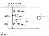
So, the sound is only distorted when the power is going through it. Could this be a problem with the virtual earth or something? That's a complete guess, but I've seen mention elsewhere of problems with the virtual earth, and it was the first thing that popped into my head when I only heard it when the power was on. R32 and C12 are to do with the virtual earth, so I'll check those.
So, the sound is only distorted when the power is going through it. Could this be a problem with the virtual earth or something? That's a complete guess, but I've seen mention elsewhere of problems with the virtual earth, and it was the first thing that popped into my head when I only heard it when the power was on. R32 and C12 are to do with the virtual earth, so I'll check those.
R32 and C12 are simply to tie the chassis to the circuitry.
The virtual earth is this section and all it does is 'balance' the voltages across the two large reservoir caps. You can measure the rail voltages from speaker ground and they should be approximately equal and opposite in polarity. Or just measure across each of the reservoir caps. Both should be the same.
You need a proper scope to look at what is happening") but see what those voltages are first.
but see what those voltages are first.
The virtual earth is this section and all it does is 'balance' the voltages across the two large reservoir caps. You can measure the rail voltages from speaker ground and they should be approximately equal and opposite in polarity. Or just measure across each of the reservoir caps. Both should be the same.
You need a proper scope to look at what is happening
but see what those voltages are first.Attachments
I checked all the voltages against the ones listed on the schematic yesterday, and all seemed fine.
When I'm measuring the rail voltages or across the reservoir caps as you mention, should I put dummy loads on the outputs?
And yes, I'm going to finally break out the scope. Let's hope it can be useful even with its limited bandwidth.
When I'm measuring the rail voltages or across the reservoir caps as you mention, should I put dummy loads on the outputs?
And yes, I'm going to finally break out the scope
. Let's hope it can be useful even with its limited bandwidth.Having a load shouldn't alter the voltages providing that the amp output has no DC offset.
This is where it gets a bit different with the 306 and its virtual ground because if there is an offset and if you add a load then all that should happen is that the voltage on the two reservoir caps will shift proportionately. So if the voltage on one went up the other would have to go down to maintain the total supply voltage figure.
I would say with NO load attached you should be able to measure zero volts DC between the speaker terminals. If that is OK then adding a dummy load will not change the rail value and ratios.
It doesn't look like there's any dc offset at outputs, and the voltages on the caps mirror each other on each channel.
I've got the scope set up, and when playing a 1000Hz sine wave, I can see a nice clean sine wave on the scope at the input, a clean one at SK2 output on the right channel, but a sawtooth or triangle at SK2 on the left channel. I'm going to keep prodding around.
I've got the scope set up, and when playing a 1000Hz sine wave, I can see a nice clean sine wave on the scope at the input, a clean one at SK2 output on the right channel, but a sawtooth or triangle at SK2 on the left channel. I'm going to keep prodding around.
That sounds strange. Make sure the scope and generator (or whatever you are using) is giving something like a couple of volts peak to peak output as measured at the speaker terminals. Without seeing it it can be a bit of an unknown so lets get some reasonable values set.
Also make sure the sawtooth/triangle wave is actually a distorted version of the input and not something being generated by the amp itself.
If you have no input present then the output should be clean (nothing there).
One for tomorrow I think
Also make sure the sawtooth/triangle wave is actually a distorted version of the input and not something being generated by the amp itself.
If you have no input present then the output should be clean (nothing there).
One for tomorrow I think
- Home
- Amplifiers
- Solid State
- Quad 306 buzz in right channel