Both T11 and T12 are completely dead, as far as I can tell. I've just ordered replacements. Thanks for pointing that out!
I'm still here 🙂 Been a busy day. I'll have a closer look in an hour or so.
Thanks! Take your time
Both T11 and T12 are completely dead, as far as I can tell. I've just ordered replacements. Thanks for pointing that out!
That sounds unusual but if there are zapped then they would absolutely cause weird unbalanced rails. I can't really see anything that could contribute to their failure. Interesting.
We will have to see what the state of play is when they are replaced.
Somehow I had my meter on the wrong setting, so I think they're fine, actually. I took out the ones from the other channel to double-check I'm testing them correctly, and they're testing the same as those.
OK, I thought it odd about those transistors.
Quick bit of info on what actually happens which might help with your understanding with regard to faut finding:
The transformer and bridge are conventional. Normally we would then have a single reservoir cap across the bridge output to produce a single rail DC supply.
In the case of the Quad that reservoir cap is actually two series connected ones. So you still have a 'single rail supply' as measured across the bridge but with a centre tap on the caps.
If the caps were 4700uF each then you now have a 'single' cap of half that across the rail i.e. 2350uF.
So far so good. The centre point of the caps will 'float' to half the total supply voltage but will only do so provided both caps are 100% identical in every way such as leakage current.
In order to make the centre point stable we could add a resistor across each cap. If the values are identical then the voltage split is 50:50. We can set any ratio we want by altering one or other value. It is just ohms law with two resistors across a DC voltage.
We now take the centre point as our reference point or what we will call ground from now on. So if we measure from the centre point to the top cap we see half the total supply voltage and if we measure to the bottom we see again half the total supply voltage. The first reading is a positive value, the second a negative.
So we have created a split or dual supply from a single using two resistors.
The resistors have to be low enough in value to swamp any normal leakage in the caps, in other words to take differing leakage values out of the equation.
The Quad uses the two series resistors R28 and R29. These are unequal by design simply to allow the Quad to appear to clip symmetrically at full output. Its a minor detail in the design and gives slightly unsymmetrical rails.
By adding the transistors and the 2k2's this artificial 'midpoint' has the ability to be able to allow a little current to be sourced or sunk into the midpoint from either of the two rails than the highish value resistors alone would allow.
The 2k2's place a limit on how much current can be sourced/sunk. The transistors in effect mean the resistors setting the voltages (the 10k and 9k1) can be quite high value and so dissipate little power. If a bit more current is needed the transistor and 2k2's do the work.
If the rails (as measured from the midpoint which is our new ground reference) are unbalanced then that means something is pulling or pushing current into that point that exceeds the ability of the 2k2 to meet.
The amp circuit itself has very few points in it that could do that.
Thinking on the hoof...
The resistors supplying the opamp and Zeners could do this if one became high. It might still work in supplying enough to the Zener but could unbalance the overall split of the rail. Worth looking at. There are four of them per channel.
Other low impedance paths could be a fault through L1 and R13 (is it??) via R22, R24 and L3 caused by a problem in the driver stages.
The current difference needed to unbalance the rails is small. In other words if the amp tries to pull 100 milliamps from the plus rail and 20 milliamps from the negative then that will unbalance things.
Wow, thank you for that incredibly detailed explanation, I'm going to save that somewhere to go over a few times again. That's really helpful for helping me learn about these things, and with this amp in particular.
I noticed yesterday that the opamp area, Zerners D1 and D2 were very hot compared to the other channel. I'm not sure if it was the Zerners giving off the heat or the resistors around it, so I'll start off with the resistors around it like you mentioned.
I noticed yesterday that the opamp area, Zerners D1 and D2 were very hot compared to the other channel. I'm not sure if it was the Zerners giving off the heat or the resistors around it, so I'll start off with the resistors around it like you mentioned.
I should probably also mention that I've got 100nF decoupling caps for zerners D1-D4 and C7, as per Dada electronics kit. These all worked completely fine for a long time, but I'm not sure if these will influence anything with my fault finding.
You're welcome 🙂
Unbalanced rails would overheat both the Zener and Resistor on the rail where the voltage increased and the other pair on the other rail would run cooler because of less voltage. So that is just a symptom of a problem rather than the cause although a resistor gone high feeding a Zener would unbalance things.
The Quad is designed so that the quiescent current draw on each rail should be similar.
Gota go... its another of them days 🙂
I wasn't sure which 4 exactly you were talking about, so I took the 5 out I could see that were going to the opamp.
R3 was spot on, R4 3.35K (a little bit scorched, but fine), R6 120K (good), R7 21.9K (good) and R33 2.21M (good).
R6 is 120K in the Quad manual, whereas with the Dada upgrade they say R6 should be 62K, I think someone else said this is to mirror if you change R13 to modify the input sensitivity. However, others suggested I should keep this as 120K and this is what I've done.
I'll check those other bits now.
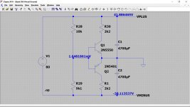
Unbalanced rails have to be caused by a current high enough to overcome the ability of the virtual ground to source or sink that current.
Let me try something... just going to knock up a quick simulation to see.
Let me try something... just going to knock up a quick simulation to see.
So it works as expected...
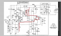
Looking at how much current is needed to unbalance things and I think the most likely path is going to be this one. The other things I mentioned just won't pass enough current to unbalance it as much as I think you measured earlier.
Looking at how much current is needed to unbalance things and I think the most likely path is going to be this one. The other things I mentioned just won't pass enough current to unbalance it as much as I think you measured earlier.
Attachments
Thanks. I also checked L1, R13, R22, R24, R25, R33, L3 and C9 and all these were fine.
You say that there could have been a fault through here caused by a problem in the driver stages, is this T7, T8, T9 and T10?
You say that there could have been a fault through here caused by a problem in the driver stages, is this T7, T8, T9 and T10?
So it works as expected...
Looking at how much current is needed to unbalance things and I think the most likely path is going to be this one. The other things I mentioned just won't pass enough current to unbalance it as much as I think you measured earlier.
Fantastic! I'll check along this path.
I'm just trying to try and think it through and how much imbalance is needed to pull it right off.
Can you just confirm again what voltage you see on the positive rail (that is R23) and what voltage on the negative rail (R20) and then I'll try and put some numbers into it.
Measure from the virtual ground point which is the junction of the two reservoir caps. Any of the ground points in the amp should be OK.
Ah, we might have something! T5 and T6 seemed fine, but T7 when I put positive lead on collector and negative on emitter I get a reading of 0 and my meter lights up red and bleeps on the diode test, whereas I would expect it to read OL if it was fine. I use this methodology for testing transistor: https://vetco.net/blog/test-a-transistor-with-a-multimeter/2017-05-04-12-25-37-07
This is based on me getting my pins correct, though. I was testing as if it goes Base, Collector, Emitter from left to right, and this being a PNP.
I actually ordered some replacements for T7 several days ago, so hopefully they should be turning up soon.
This is based on me getting my pins correct, though. I was testing as if it goes Base, Collector, Emitter from left to right, and this being a PNP.
I actually ordered some replacements for T7 several days ago, so hopefully they should be turning up soon.
I've just got to put some components back in and I'll do that. I shouldn't be turning it on at all without all the components in, should I? Just thought I should check
With a load, R20 -76.2V, R23 2.6V from the virtual ground point. R31 starts smoking almost immediately. Also, just to check, the junction between C10 and C11, I can just put my black lead on one of the pins that are joined together by the track on the board? The results were exactly the same measuring from this place and where I normally put my black lead, the screw next to R32 and C12.
Last edited:
- Home
- Amplifiers
- Solid State
- Quad 306 buzz in right channel