I swapped over the T7s and now the voltages are fine in the channel that had the fault, and the same incorrect voltages are now in the other. A replacement for T7 is hopefully turning up tomorrow morning. Hopefully that sorts the problem.
My only worry is that there was a loud hum (in both channels I think) separate to the distortion issue. So there might still be a problem to sort out yet. I've got a few things I've got to do now, but I'm going to take another look at it all later.
Thanks so much for your help, it's been incredibly helpful, and also enjoyable working this all out!
Excellent, that sounds very promising. T7 is the final output transistor in the Class A amplifier section and will run hot making it a prime candidate for failure.

Yes, fingers crossed. I want to have a prod about with my scope, but I'm conscious of components burning out on the other channel, now that I've got the faulty transistor on the other channel. Is it safe to only have one input cable (left) and only one load attached (left output) and play signals into it? Would this avoid burning up R31 and others on this channel?
Also, I've got another question about one of the components, if you don't mind. In the Dada electronics upgrade kit, they say to change R6 from 120K to 62K. Another user on here said that this is done to mirror the AC gain change when you change R13 from 9.1R to 18R or 27R, when you change R13 to lower the input sensitivity. Someone told me to keep it at 120K, whilst I was trying to fix my previous problem about a month ago, but I'm wondering if I should change it to 62K. Do you have any opinions on this?
I also bought another 306, just in case this was going to take a long time to fix, but also in case I wanted to convert the two to monoblocks. It looks quite straightforward, for one box: connect the two channels in parallel, remove one of the virtual ground sections, add a multiturn trimmer to input and some resistors at the output.Quad Spot: Quad 306 - 606 Monoblock & Virtual Earth
I know the basic advantages of using monoblocks, but can you see any obvious issues with doing this?
Sorry about asking another load of questions! If you're busy please take your time, you've already helped me enough! Thanks.
I think for my question about how to scope around one channel without the fault at T7 damaging anything, I'm going to disconnect the two wires coming from the transformer to the faulty channel, cap those wires and electrical tape. I hope that is relatively safe?
Yes, it should be safe to run with just one channel.
I'll have to study the gain change question/resistor question.
It should be fine to isolate the transformer as you suggest, in fact just removing one wire should suffice.
Important thought... your scope is probably mains grounded via the mains lead. This means that the probe ground lead has the 'ability' to become a shorting link if connected to points in the amp not at mains ground.
I'm looking at the circuit and it looks fine. The mains ground is connected to the virtual ground so all good. If you connect the scope to the virtual ground then the 10 ohm R32 is shorted out via the scope connection (if that makes sense).
If you are not used to using a scope then this is something to be critically aware of. If you connected the ground clip of the probe to say the plus rail then you short the plus rail to ground via the scope. You'll soon get used it and if in doubt measure the voltage between the two first before connecting.
If you connect the scope to the virtual ground then the 10 ohm R32 is shorted out via the scope connection (if that makes sense).
And which should be fine doing that because there is no voltage difference across that 10 ohm.
Also, I've got another question about one of the components, if you don't mind. In the Dada electronics upgrade kit, they say to change R6 from 120K to 62K. Another user on here said that this is done to mirror the AC gain change when you change R13 from 9.1R to 18R or 27R, when you change R13 to lower the input sensitivity. Someone told me to keep it at 120K, whilst I was trying to fix my previous problem about a month ago, but I'm wondering if I should change it to 62K. Do you have any opinions on this?
I also bought another 306, just in case this was going to take a long time to fix, but also in case I wanted to convert the two to monoblocks. It looks quite straightforward, for one box: connect the two channels in parallel, remove one of the virtual ground sections, add a multiturn trimmer to input and some resistors at the output.Quad Spot: Quad 306 - 606 Monoblock & Virtual Earth
I know the basic advantages of using monoblocks, but can you see any obvious issues with doing this?
Sorry about asking another load of questions! If you're busy please take your time, you've already helped me enough! Thanks.
So R6, I'll be honest and say that's a difficult one to make a definite decision on. C4, R6 C2, C1 and R1 all interact to some extent. They are all to aid in stability and altering anything around here could affect the stability margins.
If you halve the gain should you halve the value of the resistor?... I think there is probably more to it than that. Doing that also add more noise and unwanted signal (what little there is but even so) from the opamp which is used as a DC servo.
It looks a simple question but its not 🙂
Running two channels in parallel needs the usual precautions. Any slight difference in output voltage of the two amps means they fight each other with large circulating currents flowing between the amps. Output resistors mitigate that a lot all other things being equal.
If its been done successfully then fine... but it just seems an unlikely thing to do with an amp like the Quad I suppose.
Yes, it should be safe to run with just one channel.
I'll have to study the gain change question/resistor question.
It should be fine to isolate the transformer as you suggest, in fact just removing one wire should suffice.
Important thought... your scope is probably mains grounded via the mains lead. This means that the probe ground lead has the 'ability' to become a shorting link if connected to points in the amp not at mains ground.
I'm looking at the circuit and it looks fine. The mains ground is connected to the virtual ground so all good. If you connect the scope to the virtual ground then the 10 ohm R32 is shorted out via the scope connection (if that makes sense).
If you are not used to using a scope then this is something to be critically aware of. If you connected the ground clip of the probe to say the plus rail then you short the plus rail to ground via the scope. You'll soon get used it and if in doubt measure the voltage between the two first before connecting.
Thank you for explaining that to me. Yes, the scope is mains grounded. You say it should be safe for the amp to just run with one channel, just to confirm, does that mean it's ok to have no load attached to the channel that doesn't have anything plugged into the input? I ask this because R31 and others only started to burn when a load was attached? But I think I'll probably just isolate the transformer on that side just to be safe. Thanks.
R31 burns because the rails becomes unbalanced with the load attached as the amp forces current into the virtual earth.
Isolating it is probably best because even with no load it is still not right, just not as bad for R31.
Isolating it is probably best because even with no load it is still not right, just not as bad for R31.
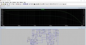
Quite an interesting amp the 306. I was curious enough to throw a rough simulation of the whole thing together.
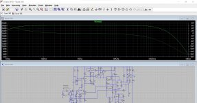
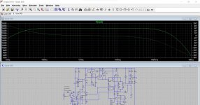
Image 1 is the standard 306, image 2 is with 27 ohm gain set resistor and image 3 is with 27 ohm plus reducing the 120k to 62k (for some reason I used 61k... that won't make a difference)
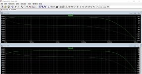
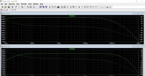
Image 4 is standard amp (top half of image) vs 27 ohm (lower half of image).
Image 5 is standard amp vs 27 ohm and 61k.
You can see the HF stability margins remain essentially the same but the reduction to 61k does influence the LF response of the amp which is expected because of the combined effect of the resistor and the 100nF input cap.
Image 1 is the standard 306, image 2 is with 27 ohm gain set resistor and image 3 is with 27 ohm plus reducing the 120k to 62k (for some reason I used 61k... that won't make a difference)
Image 4 is standard amp (top half of image) vs 27 ohm (lower half of image).
Image 5 is standard amp vs 27 ohm and 61k.
You can see the HF stability margins remain essentially the same but the reduction to 61k does influence the LF response of the amp which is expected because of the combined effect of the resistor and the 100nF input cap.
Attachments
Wow, I'm going to have to follow your guide in your sig and get to know this software.
I should have probably mentioned that some of the caps' values changed with the Dada kit, they are as follows:
Copy and pasted from Dada manual:
2 x R 62K 1% for R6 (blue-red-black-red-brown)
̶2̶ ̶x̶ ̶R̶ ̶1̶8̶R̶ ̶1̶%̶ ̶f̶o̶r̶ ̶R̶1̶3̶b̶ ̶(̶b̶r̶o̶w̶n̶-̶g̶r̶e̶y̶-̶b̶l̶a̶c̶k̶-̶g̶o̶l̶d̶-̶b̶r̶o̶w̶n̶)̶ ̶(̶*̶)̶
2 x R 27R 1% for R13c (red-violet-black-gold-brown) (*) <-- This one
2 x C 330nF MKT for C2
2 x C 1µF MKT for C3
10 x C 100nF MKT (Decouple1 caps for the zener’s D1 to D4 and C7)
6 x C 330pF polystyrene for C1, C5, and C6
2 x C 180pF polystyrene for C4
2 x C 47pF polystyrene for C8
4 x C 6800µF or 4700uF, 50V or 63V for C10 and C11
2 x C 100µF 63V for C7
All of those have been done on my unit except for R6, which is still at the original 120K.
Would changing the 100nF to 300nF as above (or any others) change either the HF or LF freq response for the better?
Also, just to clarify with the graph, ideally what you would want here is a nice flat curve stretching horizontally as long as possible each way, and with not very steep roll offs, right? Could you also please explain what the two different lines are (are they L/R?) and also what it means when they intersect?
I've downloaded LTspice so I might give it a go with the different upgrade component values this afternoon. Thanks!
Last edited:
The solid line is the amplifier output vs frequency... frequency response if you like. Gain is shown at the left in db. So you can see the effect of increasing the feedback return resistor and the gain dropping.
If you look at the last image you can see the standard amp has pretty much flat gain to around 30Hz while the altered one with 27 ohm and 61k has the gain falling away at about 90Hz.
The dotted line is phase.
I'll have to look at the other mods later, also the sim is one of the more frustrating ones 🙂 because it has problems 'converging' meaning it takes it a long time to find the operating points and 'solution' to display the results. I'll have to look at that later. I made a couple of assumptions with the current sources CR1 and CR2 which need looking at.
That's why I haven't posted the simulation file as yet 🙂 It's a tough one to crack is this.
Some progress. As you are unused to LT I've posted two files. One will show the amp producing 4 volts peak (so 2.83 rms) into 8 ohm which is 1 watt. The second is the AC analysis showing the response.
Both files use default LT models and should click and run. You need to probe the output to see the signal.
Just right click a blank area of the workspace and click run to to run the sim.
Both files use default LT models and should click and run. You need to probe the output to see the signal.
Just right click a blank area of the workspace and click run to to run the sim.
Attachments
Wow, this is great, thanks for sharing. I'm going to have a play around with it and get my head around it.
Is there any point in adding minor values such as resistor Power etc?
Is there any point in adding minor values such as resistor Power etc?
I've altered some of the cap values to match what's actually in mine, and it's improved the bass response (I think).
All default values apart from R13 changed to 27R (R6 still 120K): https://i.imgur.com/STpaGjw.png
Caps changed to match Dada electronics manual, R13=27R and R6 lowered to 62K: https://i.imgur.com/uKqFkAd.png
All default values apart from R13 changed to 27R (R6 still 120K): https://i.imgur.com/STpaGjw.png
Caps changed to match Dada electronics manual, R13=27R and R6 lowered to 62K: https://i.imgur.com/uKqFkAd.png
The power supply in the sim is 'perfect' at the moment because it is set up as a DC source with perfect characteristics. If the amp draw 1 Gw (giga watt) the supply will provide it, all without burning a hole in your screen 🙂
There is no mains ripple for example but non of that matters for what you were looking at.
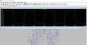
A good test on stability is to look at how squarewaves are handled and they look fine. This is with the Dada mods at 25kHz.
Using poly caps for all the tiddlers is a good move.
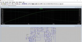
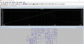
Altering C3 won't do much apart from increasing the time the DC servo around the opamp needs to settle. You can see the effect on LF performance by deliberately making the cap to small and looking at the very low frequency end of the scale.
This is 0.1 Hz to 100Hz and going from 1uF to 0.1uF
Bigger power supply reservoir caps in practice will make little difference I suspect. The original values might seem small but they are for just one channel remember. Also going to big on cap sizes can give the transformer a harder time as the lower ripple voltage means the bridge rectifier and transformer have still to put the same energy back but over a shorter time period. Again in practice it probably isn't an issue in practice but just be aware that what seems a good idea in one respect often has downsides in another.
There is no mains ripple for example but non of that matters for what you were looking at.
A good test on stability is to look at how squarewaves are handled and they look fine. This is with the Dada mods at 25kHz.
Using poly caps for all the tiddlers is a good move.
Altering C3 won't do much apart from increasing the time the DC servo around the opamp needs to settle. You can see the effect on LF performance by deliberately making the cap to small and looking at the very low frequency end of the scale.
This is 0.1 Hz to 100Hz and going from 1uF to 0.1uF
Bigger power supply reservoir caps in practice will make little difference I suspect. The original values might seem small but they are for just one channel remember. Also going to big on cap sizes can give the transformer a harder time as the lower ripple voltage means the bridge rectifier and transformer have still to put the same energy back but over a shorter time period. Again in practice it probably isn't an issue in practice but just be aware that what seems a good idea in one respect often has downsides in another.
Attachments
Although mine has had to dada upgrade done, I think it was a previous revision of the upgrade, as all the caps seem to be MKT, not polystyrene. There are some fairly cheap polystyrene ones listed on ebay, so I might go for those, to replace the ones listed in their instructions. They're pretty expensive otherwise if buying from one of the big online places.
The replacement transistors still haven't turned up yet, so I'm currently using my new 306 with the dada components transplanted from my old one. The transistors seem to be bolted or welded on my new one. In this new one, the previous owner had 8200uF reservoir caps installed, and I was a little concerned about this, especially since now you've pointed out how the transformer might be strained.
I might swap them out for the Panasonic 6800uF ones in the other. Also, the plastic wrapper on the 8200uF (Nichicon AG Gold Tune) caps seemed really cheap, really small and really light, so I'm a bit concerned they might be fake. I've tested their capacitance and they're fine, and checked their datasheet and the dimensions seem fine, but I think I'll swap them out for the aforementioned reason and for peace of mind with this one.
I also noticed that some resistors were missing from the LT files you posted, such as R24-R27. Were these omitted for a particular reason? I think I'm going to start from scratch and build it again so I can get the hang of it, and add in extras like the 100nF coupling caps across the diodes.
Last edited:
Well spotted with R26 and C9, I've missed those. R24 and R25 (in my circuit copy) are two 22 ohm in series and so I just used a 44 ohm in the sim. R27 just feeds an LED indicator so no point adding that one.
The MKT's are decent enough in larger values. Polyprops have got very expensive in small pF sizes but they are to be preferred and are way better than say ceramics.
The big reservoir caps really need to be chosen for their ripple current rating, and yes, some modern ones are very lightweight compared to those of years ago.
Ah, ok, I was searching for R24/R25 using Ctrl+F, so that's why.
The ripple current rating is marginally higher with the Panasonic caps I had previously, so I'll stick with those.
The ripple current rating is marginally higher with the Panasonic caps I had previously, so I'll stick with those.
- Home
- Amplifiers
- Solid State
- Quad 306 buzz in right channel