The maximum current tested on a continuous pure resistive load was 4,13 A at 55Vdc output, 61,5V input, for aprox 3 minutes. These are extreme conditions. It can't happen while listening music on speakers, to actually see 4 Amps current absorbed per rail.
🙂 Claiming "best evar PS", you almost have to be...I can't be an expert in everything ... but it is more important the length of Q17 mosfet terminals then of the Sigma 22. And they are longer almost to entire lenght of those transistors because I can't have access to the screws.
//

yes, it could be even better with ceramic ... there are no special components as in Q17 where everything needed to be highest quality. Sure, use ceramic.
In the 2000s when the circuit was created the COGs were very expensive. Today a 3.9nF COG costs less than an MKT of the same value. The Kemet reference given in the circuit is also NFND.
By the way, is this capacitor to prevent oscillation?
Stef.
By the way, is this capacitor to prevent oscillation?
Stef.
If we don't know what it's really for, I won't change anything then.
I wanted to make this small modification to the PCB because Q12 and Q13 are a little far from the transistor if it is to avoid oscillation.
By the way at 4A, were the white sugars hot?
Stef.
I wanted to make this small modification to the PCB because Q12 and Q13 are a little far from the transistor if it is to avoid oscillation.
By the way at 4A, were the white sugars hot?
Stef.
Attachments
Found this.
Stops oscillation to speak simply.
https://www.diyaudio.com/community/threads/what-is-the-capacitor-from-base-to-collector-for.144603/
I would look with the prototype but we should be able to use a COG here.
Stef.
Stops oscillation to speak simply.
https://www.diyaudio.com/community/threads/what-is-the-capacitor-from-base-to-collector-for.144603/
I would look with the prototype but we should be able to use a COG here.
Stef.
What is white sugars ?By the way at 4A, were the white sugars hot?
Stef.
It's good. It was the goal. 😉
Plus, I like BPRs. It takes up less floor space than a 3W and they are low inductance.
I'm not making any progress on the LTspice. I can't simulate the E-202/E-562. I couldn't find spice files too.
Stef.
Plus, I like BPRs. It takes up less floor space than a 3W and they are low inductance.
I'm not making any progress on the LTspice. I can't simulate the E-202/E-562. I couldn't find spice files too.
Stef.
4A into 8 ohms is 32W peak value. For music that corresponds to about 23Wrms.The maximum current tested on a continuous pure resistive load was 4,13 A at 55Vdc output, 61,5V input, for aprox 3 minutes. These are extreme conditions. It can't happen while listening music on speakers, to actually see 4 Amps current absorbed per rail.
Half of that in 4 ohms. Not really extreme.
Jan
What is your objective on this subject Jan?
What I can say is when you listen to music at normal level at home, in your living room, you only consume a few Watts in reality.
These continuous consumption tests only serve to prove that the board does not explode or collapse if used. You don't have to look any further. The rest will be done in the real world, by trying it used with an amplifier board (and measuring it too).
We're not there yet. Don't bury the man before he arrives. 😉
Stef.
IMO, a linear regulator is good for powering all but the output stage. The regulator can replace the RC filtering in existing designs. The amplifier will need clamping diodes to clip properly.
Ed
Ed
Hello,
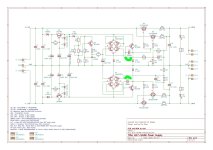
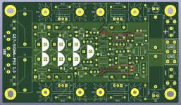
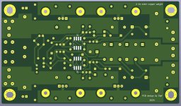
I published version 1.1 of the PCB.
The footprints for U1 and U2 (ZHB6792TA) was wrong. I confused SM-8 and SOT-8 when it was SOT-223-8. I also took the opportunity to modify some component placements and strengthen the thickness of some tracks.
The board test will not be for this week. 👽
Stef.
I published version 1.1 of the PCB.
The footprints for U1 and U2 (ZHB6792TA) was wrong. I confused SM-8 and SOT-8 when it was SOT-223-8. I also took the opportunity to modify some component placements and strengthen the thickness of some tracks.
The board test will not be for this week. 👽
Stef.
Attachments
Hello again,
By the way, I'm looking for 2 components in SPICE to complete a simulation of the circuit in LTSpice.
I'm missing the E-202 and E-562. I found the model of an E-510 that I put in the sig22 circuit and it "works".
https://www.semitec-global.com/products/crd_e_series/
So I repeat my call that I made on another Thread, I'm looking for them. 😉
Stef.
Hello,
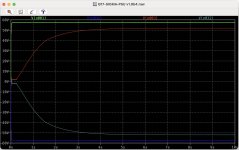
The simulation starts to work. I still haven't found the spices for the E-502/E-562 but I cobbled together a simulation with a NJFET+R instead.
Regards,
Stef.
Curve : input = 57.1Vdc - output = 51.5Vdc - current = 1A
The simulation starts to work. I still haven't found the spices for the E-502/E-562 but I cobbled together a simulation with a NJFET+R instead.
Regards,
Stef.
Curve : input = 57.1Vdc - output = 51.5Vdc - current = 1A
Attachments
Last edited:
- Home
- Amplifiers
- Power Supplies
- Q17 Sigma22 Regulated Ultrastable Ultralow Noise Linear Power Supply +-50/60Vcc