
Do you have a link to the files? I am new to Github....Hello,
Kicad files and Gerber files uploaded to the Github repository.
Have fun.
Stef.
Hello,
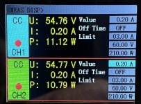
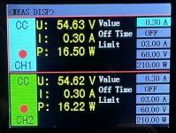
I did a test at 60V input 200mA load with an electronic load. I can't measure. The device full of MOSFET disrupts the measurement.
I need to see if I can find power resistors that would at least allow me to test the ripple at 200mA.
I'll do heat and voltage loss tests based on amperage instead.
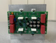
At 200mA, the SK104-50 heatsinks are at 30/32°C after 1 hour (room at 20°C).
The bet of a board which holds 200mA with its heatsinks on the PCB seems to have been met. I still have to have some room (15W in theory). I will push to stabilize them around 40°C.
Stef.
I did a test at 60V input 200mA load with an electronic load. I can't measure. The device full of MOSFET disrupts the measurement.
I need to see if I can find power resistors that would at least allow me to test the ripple at 200mA.
I'll do heat and voltage loss tests based on amperage instead.
At 200mA, the SK104-50 heatsinks are at 30/32°C after 1 hour (room at 20°C).
The bet of a board which holds 200mA with its heatsinks on the PCB seems to have been met. I still have to have some room (15W in theory). I will push to stabilize them around 40°C.
Stef.
Attachments


Hello,
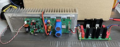
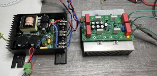
After several days of operation with an amplifier board, the SIgma board is good for service. I didn't find any problem with it. Everything seems to work well both when measuring with a scope and when listening.
Happy experimenting if you decide to build it.
Stef.
After several days of operation with an amplifier board, the SIgma board is good for service. I didn't find any problem with it. Everything seems to work well both when measuring with a scope and when listening.
Happy experimenting if you decide to build it.
Stef.
Attachments

In French, we have masculine and feminine for objects. So, I made a mistake while writing. 😉
"board" is feminine, yes.
I was only able to torture it up to 1A in the end due to lack of components.
"board" is feminine, yes.
I was only able to torture it up to 1A in the end due to lack of components.
Follow the thread with interest.
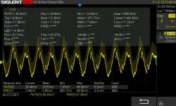
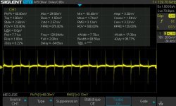
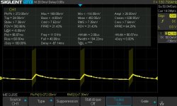
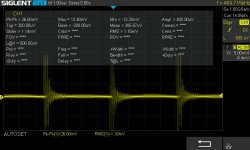
Do I read this correctly? The pk2pk value is reduced from around 270 mV to 60mv and the RMS from around 7,4 mV to 3,1 mV?
Do you think this can be improved?
Do I read this correctly? The pk2pk value is reduced from around 270 mV to 60mv and the RMS from around 7,4 mV to 3,1 mV?
Do you think this can be improved?
Hello,
If you increase the voltage difference you can lower it further. On the first measurement, I was just on the verge of stalling.
In the first measurement, I was at 60V input and 54V output.
If I go to 62V input for 54V output. Measurement is better. I think as you continue to increase the difference, the measurement will get even better. You just have to find the right position neither too much nor too little depending on the power supply in front and the consumption / voltage behind.
Stef.
EDIT: you have to play around with the settings on the SMPS and on the Sigma.
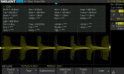
In the second curve. 58V at input (mini on SMPS) and come out at 53V, diff 5V and I got 14.20pp / 1.23mV RMS.
If you increase the voltage difference you can lower it further. On the first measurement, I was just on the verge of stalling.
In the first measurement, I was at 60V input and 54V output.
If I go to 62V input for 54V output. Measurement is better. I think as you continue to increase the difference, the measurement will get even better. You just have to find the right position neither too much nor too little depending on the power supply in front and the consumption / voltage behind.
Stef.
EDIT: you have to play around with the settings on the SMPS and on the Sigma.
In the second curve. 58V at input (mini on SMPS) and come out at 53V, diff 5V and I got 14.20pp / 1.23mV RMS.
Attachments
Last edited:
Have build this power regulator and it Works Well with 60 volt input for my Q17 mini. Onde of my friends want to try it. But he uses 70 on his amp. Is the Sigma capable of handling ~77 volt input?
kind regards
kind regards
Hello,
The Sigma will not work at 77V because most of the components used are limited to 63V/65V (capacitors, BCxxx and ZHB6792TA).
For the Turbo max 60V input in the Sigma and 54V in the Turbo.
For the Turbo, I would have to update it like the Mini 3.0 but I don't have the time at the moment. In addition, there are big problems with the FQA/FQP which are no longer available and it works less well with other MOSFETs. The best would be if I try to make a Turbo with a pair of ECW20N20
and ECW20P20. it will be as powerful and simpler to build (no MOSFET sorting).
Stef.
5. The output voltage of S22 is adjustable, which is mainly determined by the chosen voltage for the Zener diode TL431, tipycal 15V up to 18V in order to got the desired output. R4//R44 has been chosen for 18V working zenner voltage. R4 alone is giving about 15V working zenner voltage and less output voltage can be adjusted. The 10K (or 20, 50 k) trimer is making a very fine tunning of the output voltage.
Is there a formula for +/- 30V?
- Home
- Amplifiers
- Power Supplies
- Q17 Sigma22 Regulated Ultrastable Ultralow Noise Linear Power Supply +-50/60Vcc