Apparently something with a potmeter.
But it does not indicate a problem, it just seems to report the various pot settings.
Or maybe an error in the pot setting syntax.
Is there a problem with the sim?
Jan
But it does not indicate a problem, it just seems to report the various pot settings.
Or maybe an error in the pot setting syntax.
Is there a problem with the sim?
Jan
Hi Jan
Have found out now. afte your reply. Looking for a solution to make the sigma being able to work for a input of 67-70volt input.
Maybe the Bc548 have to be changed?
Kind Regards
Have found out now. afte your reply. Looking for a solution to make the sigma being able to work for a input of 67-70volt input.
Maybe the Bc548 have to be changed?
Kind Regards
I am not seeing an "*.asc" file on your github repository. (You can post LTSpice *.asc files to DIYAUDIO)
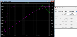
Would suggest that you hang a current source of AC=1, DC=25m on the output. If you run an AC Analysis and plot Vout/Iout you will derive output impedance. Good to know.
From the output impedance you can derive stability.
Would suggest that you hang a current source of AC=1, DC=25m on the output. If you run an AC Analysis and plot Vout/Iout you will derive output impedance. Good to know.
From the output impedance you can derive stability.

You Can read in the q17 thread where this psu was startet in. There is some calculations on the zener voltage.
Got it.You Can find it in stefs github under power supply not in the amplfier directory.
The models of the CRD's need some adjusting. For the E202, Vto = -1.4, for the E562, Vto = -2.35
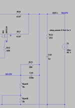
No, this design is not stable for a very simple reason. Capacitor C16 needs series resistance, even an Ohm. If you use a film capacitor here the phase margin is reduced to 31 degrees at 280 kHz. (Using the Erikson Maksimovich approximation where:
Q = f * tg * pi and
PM% =~ 50.363 * Q^(-0.907)
You could also just eliminate the capacitor as it serves no useful purpose.
Q = f * tg * pi and
PM% =~ 50.363 * Q^(-0.907)
You could also just eliminate the capacitor as it serves no useful purpose.
Attachments
Interesting. So you belive the initial design is flawed? Do you belive we Can make it to acccept 67-70volts input?
It's a flaw you see all the time from DIYr's who think more film caps are better. The remedy is quite simple.
An old fashioned AM transistor radio is helpful in testing power supplies for oscillation.
You can make an LM317 oscillate if you use only a film cap on the output node.
If you have to bypass something do it as close as possible to the sensitive stage and use a ground plane.
An old fashioned AM transistor radio is helpful in testing power supplies for oscillation.
You can make an LM317 oscillate if you use only a film cap on the output node.
If you have to bypass something do it as close as possible to the sensitive stage and use a ground plane.
Hi folks,
If you find anything that could be improved, give me a summary at the end. I'll fix it on Github when I have a little time.
There's also something I noticed: one of the polarities, the positive one, if I remember correctly, starts up slower than the other. About half a second. It would be good to try to correct that.
About the 1uF red caps at output. I know, I exaggerated a bit for aesthetic reasons, but you don't have to put them in. The 0.1uF at the input are also useless. It's a relic from the prototype that I forgot to remove.
Otherwise, in practice, the power supply is reliable and durable.
Regards,
Stef.
68V is the maximum as the ZHB6792TA is limited to 70V. It is better to keep a margin.
Of course, all capacities must be 80V as indicated in the BOM.
Thank you Steff. Will try today with my 45vac trafo. use it on my Q17 mini.
That's cutting it close. 45Vac is 45x1.4=63V peak.
Unloaded it will be more.
And the mains can be 10% high as well ...
Jan
Unloaded it will be more.
And the mains can be 10% high as well ...
Jan
That's cutting it close. 45Vac is 45x1.4=63V peak.
Unloaded it will be more.
And the mains can be 10% high as well ...
I know. My mains is stable here, so that don´t frighten me. But don´t want for now to buy new trafos, as these are from a earlier project.
But thank you for your consern.
Kind Regards
Hello,
I updated the LTSpice simulation model in my Github repository.
I fixed the models that no longer worked with last LTSpice version and added the missing libraries.
Regards,
Stef.
Q17-SIGMA-PSU-LTSpice-1.0.1
https://github.com/stefaweb/audio-psu/tree/main/Q17-SIGMA-PSU-1.1
I updated the LTSpice simulation model in my Github repository.
I fixed the models that no longer worked with last LTSpice version and added the missing libraries.
Regards,
Stef.
Q17-SIGMA-PSU-LTSpice-1.0.1
https://github.com/stefaweb/audio-psu/tree/main/Q17-SIGMA-PSU-1.1
- Home
- Amplifiers
- Power Supplies
- Q17 Sigma22 Regulated Ultrastable Ultralow Noise Linear Power Supply +-50/60Vcc