Reverse polarity can damage capacitor too, just so you be aware that you may need to change it.
Hello.
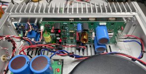
Today I installed a AUDIO GRADE transformer from Toroidy.pl (600VA primary 240V secundary 2x 36V). I can agree with the recommendations for this transformer, it is the quietest toroidal transformer I have had so far, it is just inaudibly quiet.
Regards Tim
Today I installed a AUDIO GRADE transformer from Toroidy.pl (600VA primary 240V secundary 2x 36V). I can agree with the recommendations for this transformer, it is the quietest toroidal transformer I have had so far, it is just inaudibly quiet.
Regards Tim

Welcome to the club Tim.
Another happy person.
What voltage do you get with your 36V when DC loaded?
Stef.
Another happy person.
What voltage do you get with your 36V when DC loaded?
Stef.
I have measured, it is only 90.7V between + and - from the amplifier. Mathematically this fits exactly. Voltage from inverter (accupowered): 220V, gives 2x33Vx2^0.5 = 93.33V minus the two bridge rectifiers 2.64V/4 = 0.66.
Not much, but enough that it plays nice.
Regards Tim
Not much, but enough that it plays nice.
Regards Tim
5V less still counts.
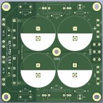
I worked on an optimized PCB version of the Q17-PSU. I especially worked on the part around the bridges and the ground plan. I still have to test it in real life but at the scope, it's very clean (1.2mVpk, 10mVrms). Even better than before. 100Hz is really very low now. I tested it at 48Vdc with a load of 1K5 per channel.
I should put the files online in a few days.
Good evening,
Stef.
Attachments
Last edited:
Hello,
I downloaded the Q17-PSU 1.0.6 files in the Github repository.
The tests were conclusive. With my Q17-Mini 2.0 amp boxed and the latest version of the power supply, I no longer have any trace of hum in the speakers (even with R32=0R and without GND/Ground filter).
Have fun!
Stef.
I downloaded the Q17-PSU 1.0.6 files in the Github repository.
The tests were conclusive. With my Q17-Mini 2.0 amp boxed and the latest version of the power supply, I no longer have any trace of hum in the speakers (even with R32=0R and without GND/Ground filter).
Have fun!
Stef.
Hello,
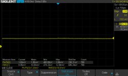
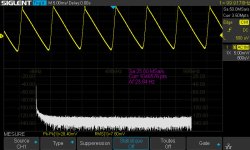
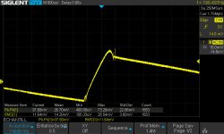
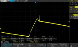
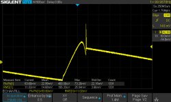
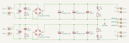
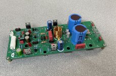
To complete the measurements of the 1.0.6 power supply, here are the measurements with Saligny Universal bridges that you can compare with those of yesterday with classic Vishay bridges.
The test was carried out with almost the same components and with a load of 1K5. The output voltage with the same transformer is 50.1Vdc.
Stef.
Attachments

Last edited:
Hi Stef,
If I compare the two measurement results from your rectifier PCB, the Vishay bridge works with a little less noise floor and has a smooth signal, or?
Do you also have a BOM with the components you used for the measurement?
Regards Tim
If I compare the two measurement results from your rectifier PCB, the Vishay bridge works with a little less noise floor and has a smooth signal, or?
Do you also have a BOM with the components you used for the measurement?
Regards Tim
Hi Tim,
These are the same values between the two boards but not the same component brand.
The measurements are not always obvious even if the scope probe is stuck to the power supply terminals like in the books. Just taking the measurements in the evening or during the day changes the results.
I think the big CDEs are better than the Wurths.
Stef.
Vishay board
D1, D2 : 625-GSIB2580-E3
C5, C6, C7, C8 : 598-SLP103M063H9P3
C9, C10 : B32922J3224K000
Saligny board
D1, D2 : Saligny Universal 55V
C5, C6, C7, C8 : C710-861020786030
C1, C2 : 810-FG28C0G2A103JRT6
C3, C4 : 598-MPX103K305D
C9, C10 : 598-MPX224K305E
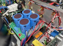
For the fun, the Saligny at work. 😉
These are the same values between the two boards but not the same component brand.
The measurements are not always obvious even if the scope probe is stuck to the power supply terminals like in the books. Just taking the measurements in the evening or during the day changes the results.
I think the big CDEs are better than the Wurths.
Stef.
Vishay board
D1, D2 : 625-GSIB2580-E3
C5, C6, C7, C8 : 598-SLP103M063H9P3
C9, C10 : B32922J3224K000
Saligny board
D1, D2 : Saligny Universal 55V
C5, C6, C7, C8 : C710-861020786030
C1, C2 : 810-FG28C0G2A103JRT6
C3, C4 : 598-MPX103K305D
C9, C10 : 598-MPX224K305E
For the fun, the Saligny at work. 😉
Attachments
Hello Stef,
I am trying to understand your results.
The needle pulses from the active rectifiers is of course poison to the Q17, so normally the active rectifiers also call for pulse capacitors in the output to neutralize such things, according to the datasheet.
I bought four of the CDE 380LX123M063A052 and soldered them to the amplifier boards. According to the measurement of the component tester, the ESR of the CDE is rather higher and the bass is o.k. but not more. The CDE of you, the SLP103M063H9P3 are described with even higher ESR in the datasheet. Therefore, I would expect that if you compare the rectifier boards in the amplifier, so if you connect your big speakers to the amplifier and listen to music, then I would expect your CDE only on the basis of the information in the data sheet, that the rather restrained in the bass perform.
Tim
Hi Tim,
I'm planning to compare the different PSUs but I'm not ready yet. I need to upgrade them all to 1.0.6 first.
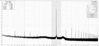
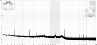
I put the Q17-Mini 2.0 boxed through the REW reel again. With the new power supply 1.0.6. PCB, I lowered the 50Hz from -85dB to -120dB. 😉
This is the Vishay bridge + CDE SLP power supply which is in the Mini box now.
Stef.
I'm planning to compare the different PSUs but I'm not ready yet. I need to upgrade them all to 1.0.6 first.
I put the Q17-Mini 2.0 boxed through the REW reel again. With the new power supply 1.0.6. PCB, I lowered the 50Hz from -85dB to -120dB. 😉
This is the Vishay bridge + CDE SLP power supply which is in the Mini box now.
Stef.
Attachments
I updated the Michicon Muse KG to version 1.0.6. 😉
I put v1.0.6 Vishay bridge + Vishay BC 256 in the boxed Turbo. I'm going to listen to them for several days and then switch to the Muse version to see if I hear a difference.
Stef.
I put v1.0.6 Vishay bridge + Vishay BC 256 in the boxed Turbo. I'm going to listen to them for several days and then switch to the Muse version to see if I hear a difference.
Stef.
Attachments

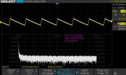
Am really qurious about what make these spikes? Mosfet noise?Hi Tim,
These are the same values between the two boards but not the same component brand.
The measurements are not always obvious even if the scope probe is stuck to the power supply terminals like in the books. Just taking the measurements in the evening or during the day changes the results.
I think the big CDEs are better than the Wurths.
Stef.
Vishay board
D1, D2 : 625-GSIB2580-E3
C5, C6, C7, C8 : 598-SLP103M063H9P3
C9, C10 : B32922J3224K000
Saligny board
D1, D2 : Saligny Universal 55V
C5, C6, C7, C8 : C710-861020786030
C1, C2 : 810-FG28C0G2A103JRT6
C3, C4 : 598-MPX103K305D
C9, C10 : 598-MPX224K305E
For the fun, the Saligny at work. 😉
Mosfet noise is the wrong term. It is about the capacitance of the Mosfet. With the bridge, I don't see a film capacitor damping the needle pulse. Such a capacitance should therefore be placed on the PCB of the active rectifier to be optimally effective.

Without the capacitance of the Mosfet, the Q17 would be able to work ideally, since there is this capacitance, one sees the needle pulses also with the Q17 in the output signal - provided that it is not superimposed, as when increasing the supply voltage.
Without the capacitance of the Mosfet, the Q17 would be able to work ideally, since there is this capacitance, one sees the needle pulses also with the Q17 in the output signal - provided that it is not superimposed, as when increasing the supply voltage.
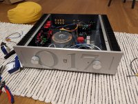
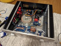
My build is finally coming along...
Im not completely happy with how the frontplate turned out, though. In the CAD it looked better with the knobs overlapping the text. I just thought, if I have to have it customized, why not make something a little special.
Now, if I only could produce a fully working second board... I'm going into my third try now.
Attachments
Hi Folks,
I released a maintenance version 1.2.3 of Q17-Turbo. The main modification is the addition of Faston connector for the power supply. I tested it in real life and found no problem. I took the opportunity to update some of the measurements.
The files are available as usual on my Github repository.
Regards,
Stef.
Version [1.2.3] (27-10-2023)
- Modified R32 footprint to support potentiometer type T93YA100KT20 (for testing).
- Added zener D7 and D5 (1N5245B) to protect output.
- Added Faston connector footprint on J3 input power connector.
- Removed useless fuse sockets to fit new Faston footprint.
- Optimized some tracks on GNDPWD parts.
- Moved T5 and T6 to a better location.
- Various adds on schematic.
- New measures with a better measurement device.
Attachments
Last edited:
Hello All,
I had the opportunity on Sunday to listen to the Q17 on corner horns. They are replicas of the large Klipsch corner horns with 38cm bass, midrange and tweeter horns. Normally the horns are driven by a Unison Research Performance tube amp. The source is a Denon SACD drive.
The difference was quite astonishing, as any coloration that usually plays the horn on the tube amp was gone, the reproduction was incredibly clear, detailed and really impressively dynamic - we listened really loud without anything being unpleasant.
My interest was in how the Q17 coped with the very wavy impedance response common with such speakers and also a lot of back induction from this. This was particularly impressive as it could really tame and guide the horn. I was very impressed, by the balance of the sound, which I have not heard from such a speaker before.
Next, the Q17 challenged a T+A V10 with two T+A A3000 power amplifiers. Here, the Q17 again clearly outperformed the existing system in terms of control and resolution and played very confidently. In the bass, it convinces with ultra depth, but is clearly more audible and controlled than the T+A. With the T+A, the bass sounds a bit thick and much more indistinct. In the treble, the Q17 can apparently again drive the demanding speakers precisely, as they now also sounded clean and linear - this was audible because with the original system, the women's voices wavered with pitch in the volume, as if the singers couldn't hit the note with the right volume.
Anyway, it's very impressive the audiophile quality of the Q17.
Tim
- Home
- Amplifiers
- Solid State
- Q17 - an audiophile approach to perfect sound