The LED in this case is a voltage regulator. That's why I use green LEDs for this, because they have a smoother curve and thus react even more stable in case of fluctuations.
The only important thing is that it is an LED that can handle enough power, any LED with 1.8 - 2V and 20mA will work, so you can understand that.
If you want your amplifier to play clearer, you can solder 2.2nF - 4.7nF to the connection wires of the LED to it, this dampens the current noise of the LED, you can hear that with my Q17 versions.
Hi all, I would like to know what is the recommended idss value for Q8 (LSK170B) on the Q17.3.
Regards.
Regards.
Hello,
There is no recommended idss as far as I know. At best, you can sort them so that the gain is the same on both boards.
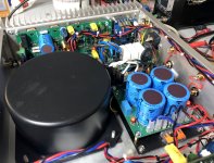
Along the way, I received the new 400VA 244Vac/2x44Vac transformer from TOROIDY. It works. I got 61Vdc with the Saligny PSU and 60Vdc with a regular bridge. I no longer have this enormous 100Hz which spoils the pleasure. I will finally be able to start the endurance tests on the Q17-Turbo in a box.
Stef.
There is no recommended idss as far as I know. At best, you can sort them so that the gain is the same on both boards.
Along the way, I received the new 400VA 244Vac/2x44Vac transformer from TOROIDY. It works. I got 61Vdc with the Saligny PSU and 60Vdc with a regular bridge. I no longer have this enormous 100Hz which spoils the pleasure. I will finally be able to start the endurance tests on the Q17-Turbo in a box.
Stef.
Attachments

Toroidy is the Rolls Royce for toroids. Very rare to have trouble from them, but you do pay a little more for it. I don't mind of course. Nice build @ steff1777!
Best,
Anand.
Best,
Anand.
Hi,
Even after years of amp assembly, we discover new ones every day.
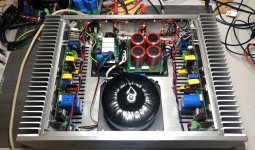
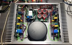
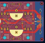
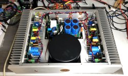
If I wire the power cables on the +60V side of the PCB, ZERO hum. 👍
As in the second pictures.
If I wire in the middle between the blue capacitors, hum, like 10cm from the speakers.
If I wire the cables on the -60V side, big hum.
From theory to practice. If someone who is a math person can explain the phenomenon, it would be great.
Good evening,
Stef.
Even after years of amp assembly, we discover new ones every day.
If I wire the power cables on the +60V side of the PCB, ZERO hum. 👍
As in the second pictures.
If I wire in the middle between the blue capacitors, hum, like 10cm from the speakers.
If I wire the cables on the -60V side, big hum.
From theory to practice. If someone who is a math person can explain the phenomenon, it would be great.
Good evening,
Stef.
Attachments
Hi Stef,
This is really a very special problem, your hum.
I have the last setup again in the too small housing and the cables simply untwisted stuffed in - because there is simply no more room for cable ties in it - and it hums nothing, it's just completely silent. I find good, my solution.
Tim
This is really a very special problem, your hum.
I have the last setup again in the too small housing and the cables simply untwisted stuffed in - because there is simply no more room for cable ties in it - and it hums nothing, it's just completely silent. I find good, my solution.
Tim
Yes, I collect them.
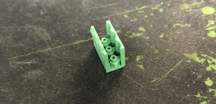
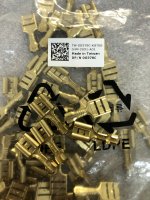
I spoke too quickly. It's the green connectors that make poor contact, not the cable thing. If I move them slightly with my fingers, the hum comes and goes and even loudly sometimes. The connector support is detached from the metal contacts. If I pull everything comes. Remains the 3 pins on the PCB. I'm good at changing them. 😡
Stef.
It's my fault. I didn't have the space to put screw terminal blocks and I put low-end pluggable connectors. I'll pay for it with two hours of dismantling.
I removed the support to see, it works much better without it. 😎
I'm already going to change the female connectors which I have had to plug and unplug a good thirty times.
Otherwise apart from that, the amp seems to work well but for the moment I only have a small pair of bookshelf to listen to.
Good night,
Stef.
I'm already going to change the female connectors which I have had to plug and unplug a good thirty times.
Otherwise apart from that, the amp seems to work well but for the moment I only have a small pair of bookshelf to listen to.
Good night,
Stef.
Attachments
Hello,
The amp is better with new connectors. I finally only changed the female connector and glued the supports to the PCB so that they no longer move. He's on an endurance test in the background music.
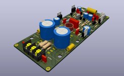
I'm thinking about a next version of the Q17-Turbo PCB with changes to the power connector (and other small changes that I'm working on).
In the current version, I use a 3-pin connector with a pitch of 5mm.
Would you be interested in switching to a 3-pin connector with a 10mm pitch?
This allows for a larger, stronger connector. I took an example with KF1000-3P connectors.
I can also double the input connector with 3 Faston connectors (same as in the Mini) on the same footprint.
If you have any suggestions, I'm interested.
I would take the opportunity to remove the fuse holders which are not of much use in practice once the board has been tested (generally after the tests, I short circuit them from below).
Regards,
Stef.
The amp is better with new connectors. I finally only changed the female connector and glued the supports to the PCB so that they no longer move. He's on an endurance test in the background music.
I'm thinking about a next version of the Q17-Turbo PCB with changes to the power connector (and other small changes that I'm working on).
In the current version, I use a 3-pin connector with a pitch of 5mm.
Would you be interested in switching to a 3-pin connector with a 10mm pitch?
This allows for a larger, stronger connector. I took an example with KF1000-3P connectors.
I can also double the input connector with 3 Faston connectors (same as in the Mini) on the same footprint.
If you have any suggestions, I'm interested.
I would take the opportunity to remove the fuse holders which are not of much use in practice once the board has been tested (generally after the tests, I short circuit them from below).
Regards,
Stef.
Attachments
Faston is better, especially if you solder it!
But copper faston are very rare.
Hello,
This is good. They exists in three cable sizes.
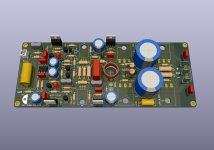
The Q17-Turbo is wired as follows: UL1007 AWG16 (1.27mm2) cables for the power supply and PTFE Silver-Plated AWG17 (1mm2) cables for the ouput speaker wire. The signal cables are made of PTFE Silver-Plated wire 24AWG (0.2mm2) twisted with a drill.
Regards,
Stef.
Attachments
Last edited:
Cute these thin cross sections.
I wire the power supply with 2.5 mm² and the speaker connections with 3mm² (with 2 or more cable). As a supply line, a high-frequency coaxial cable with 50 Ohm impedance has proven itself sonically.
Tim
I wire the power supply with 2.5 mm² and the speaker connections with 3mm² (with 2 or more cable). As a supply line, a high-frequency coaxial cable with 50 Ohm impedance has proven itself sonically.
Tim
I totally disagree Tim.
Given the powers in question and the distances involved, there is absolutely no point in having such a large cable in a chassis. Especially after finishing on a 2 Oz and 1cm wide PCB track. 😉
A coaxial cable for audio is also absolutely useless in a chassis and it is even more sensitive to interference given the short distances.
Stef.
EDIT: The Turbo is finished. It works well without noise. I'll leave it for two more days as an endurance test and I'll be able to test it on the Dynaudio.
Attachments
Last edited:
Stef,
I experiment and do hearing tests, to see what has what effect.
I also completely agree with you that the bass response can be influenced if I add wire to the power traces of the amp board. Of course, I've done this with commercial amplifiers and was amazed at how significantly this influence changes the sound.
Of course, one can want to have the amplifier softer in the sound image and use thinner cables, but that is not the objective erverytime.
Also, I have of course listened to experts like you and also with thin cables laid the feed lines and sporadically hum from the DAC or amplifier to hear. With shielded cables I could collect the experience that I have received no audible interference.
Therefore I can support my statement that it is very small resistances in the amp output that already have an audible influence on the sound image. This influence can also be calculated and simulated, but that is another story.
Tim
If we start discussing the difference in sound between cables we are not out of the woods. 😉
On another subject, I did some research on a 3-pin connector with a 5mm pitch better than those I have in stock.
I found this connectors (male female). The support has a closed shell which does not deform and the pins are 1mm2. They are reasonably priced. They are also found among the Chinese Ali shops.
Series 2EDGK and 2EDGVC (Originally manufactured by PHOENIX CONTACT).
https://www.tme.eu/fr/details/2edgk...ectables/degson-electronics/2edgk-5-0-03p-14/
https://www.tme.eu/fr/details/2edgv...ctables/degson-electronics/2edgvc-5-0-03p-14/
https://fr.aliexpress.com/item/33019472953.html
I ordered a few to see.
Have a nice week end,
Stef.
- Home
- Amplifiers
- Solid State
- Q17 - an audiophile approach to perfect sound